According to a Pakistani newspaper, though the most recent flooding is different in nature compared to the one in 2010 — the latter was a flash flood while the current is a riverine flood — in both cases, it can be argued that the damage caused by both disasters is the outcome of lessons not learnt in demography as well as unwillingness to carry out flood protection measures across Pakistan. A research carried out by this author in 2017, about 2010 floods in Pakistan, history has repeated itself because no corrective measures were taken. It was almost déjà vu in 2022 — and yet, no lessons had been learnt. After all, disaster management is more about preparedness than response.
In a case of The pot calling the kettle black, the planning minister Ahsan Iqbal is reported to have said Pakistan was feeling the effects of climate change caused by richer nations and their “irresponsible development”. While all natural disasters can be ascribed to climate change a study of the earlier research will reveal that the Pakistan government did precious little to prevent recurrence of events that could have reduced the impact of the calamity. For example almost all barrages in the country are silted up to the brim, where is the scope to cushion the floods. The government should be questioned and asked to give an account of desilting measures taken since 2010.
THE FACTS AS THEY STOOD IN 2010
The floods in Pakistan now show signs of abating but the havoc caused by them will continue to mount. It is too early to measure even the immediate losses of lives or property, both private and public, although over 2000 persons are estimated to have died and 21 million become refugees in their own country. Secondary damages to agricultural land and animal husbandry will take years to recoup. At one point about one-fifth of Pakistan’s total land area had goneunder water. Floodwaters have destroyed crops : an estimated 700,000 acres of cotton, 200,000 acres each of rice and sugar cane and 300,000 acres of wheat. This will impact the agricultural economy which contributed 20.4% of Pakistan’s GDP last year. The cascading effect into industry and trade is bound to add to economic woes.
Pak Flood affected districts as on 6th September 2010 – (Source OCHA)
Scientists have described this catastrophe as a once-in-a-century flood. Out of a Population of 168 million nearly 21 milion people have been affected by floods out of a total area of Pakistan of 796 095 square kilometers, the Flood-affected area is 160 000 square kilometers. In a country where already a large percentage of the population is living as refugees, an additional 1.85 million homes have been destroyed or damaged due to floods. Look at the fact sheet of the present disaster:
Pakistan Flood Losses (as on 6 September 2010)
Source: NDMA, PDMA
Province
Deaths
Injured
Houses Damaged
Population Affected
Balochistan
48
102
75,261
*672,171
Khyber Pakhtunkhwa
1,154
1,193
200,799
4,365,909
Punjab
110
350
500,000
8,200,000
Sindh
186
909
1,058,862
6,988,491
AJK
71
87
7,108
245,000
Gilgit Baltistan
183
60
2,830
81,605
Total
1,752
2,701
1,844,860
20,553,176
* Additional 600,000 IDPs from Sindh are living in Balochistan
The degree of severity to which people have been affected by the floods varies depending on their particular losses and damages. UN assessments have been launched in at least three provinces to identify severely affected families who require life-saving humanitarian assistance. The UN experts have identified 2.7 million people in Khyber Pakhtunkhwa, 5.3 million in Punjab and 4.4 million in Sindh that are in need of immediate humanitarian assistance.
Approximately 4 out of 5 people in the flood-affected areas depend on agriculture for their livelihood. Across the country, millions of people have lost their entire means to sustain themselves in the immediate and longer term, owing to the destruction/damage of standing crops and means of agricultural production. One of the greatest challenges on the ground is helping farmers to recover their land in time for wheat planting beginning in September/October and to prevent further livestock losses. According to the FAO figures released on 3rd September 2010, the scale of losses to the agriculture sector caused by the Pakistan floods is unprecedented and further unfolding:
The Agriculture Cluster rapid damage assessments, completed in half of all flood-affected districts, found that 1.3 million hectares of standing crops have been damaged
Countrywide damage to millions of hectares of cultivatable land, including standing crops (e.g. rice,maize, cotton, sugar cane, orchards and vegetables) appears likely
Loss of 0.5-0.6 million tonnes of wheat stock needed for the wheat planting season
Death of 1.2 million large and small animals, and 6 million poultry (Department of Livestock)
While the full extent of the damage still cannot be quantified and assessments are ongoing, the direct and future losses are likely to affect millions of people at household level, as well as impact national productive capacity for staple crops, such as wheat and rice. The FAO feels that response to needs in the agriculture sector cannot be underestimated nor delayed.
The political spillover is equally if not more worrisome. Relief efforts have highlighted the inefficiencies and corruption endemic in the Pakistani administrative set-up, magnified as it is becoming in the eyes of the already disenchanted masses, especially the internally displaced. The fear is that fundamentalist organizations will extend their grip over affected populations by filling in wide gaps in disaster relief left by Pakistan Government and international relief agencies. All this adds fuel to the already political fire in a volatile and unpredictable Pakistan.
Even if Pakistan wades through the floods, what is there to prevent another water disaster in the future? To answer this question, one must examine these floods in a broader framework. Pakistani meteorological data points to unusually heavy rains in July – August in the Khyber Pakhtunkhwa and Punjab provinces as the main cause of the floods. Satellite pictures corroborate this.
Satellite Map shows the swelling Indus River at Sukkur Barrge Source NASA
Satellite Map shows the swelling Indus River at Sukkur Barrge Source NASA
According to a WAPDA (Water and Power Development Authority) ] press release on Water Situation on 03 – 09 – 2010 the 24 hour Inflows / Outflows (in Cusecs) of the major Dams on the rivers in Pakistan were as follows:
Indus at Tarbela 203300 / 203300 Cusecs
Kabul at Nowshera 42000 / 42000 Cusecs
Indus at Chashma 249100 / 244100 Cusecs
Jhelum at Mangla 42800 / 42800 Cusecs
Chenab at Marala 87000 / 67400 Cusecs.
The above figures indicate that the Pakistani dams/barrages are virtually unable to retain any water, as can be seen above, almost all of the inflows are equal to the outflows. This is normally the case in monsoons for some dams but the figures are shocking because not a single dam except for Marala on the Chenab has been able to absorb some 20,000 cusecs of water.
Balochistan Times (August 21, 2009) reported that since the Chashma Barrage had been filled with water along with Tarbela Dam and Mangla Dam as a result of filling of these water reservoirs, IRSA had directed the provinces to use the released water as much as they needed without any restrictions. According to IRSA (Indus River System Authority) officials, besides Mangla and Tarbela Dams the approximate inflow of water in the other rivers was 319500 cusecs and 4000 cusecs from river Kabul, all of which was being released as Tarbela and Mangla had filled completely. The CJ canal had been closed so that the Chashma Barrage could be destilled. The plus side for power starved Pakistan was that with the filling of dams with water, the power production had been increased, from which about 4000MW power was being generated from hydel power, which reduced load shedding in the country..
The flood affected areas were mostly along the main Indus River and its western tributaries – Swat and Kabul; and less so from the eastern tributaries – Jhelum, Chenab and Sutlej. This should not however obscure the overall picture. More than 80% of the total water flows in the Indus river- system is accounted for by snowmelt and rainfall in the mountainous regions which are largely beyond its political control and belong to Afghanistan, India and China. According to one estimate, the Kabul river accounts for 20 to 30 MAF of total annual flows, the main Indus 100 MAF and the Jhelum and Chenab 60, while the Ravi, Beas, and Sutlej add another 40 MAF or so. Floods are a cumulative effect of all these flows.
Initially, storage dams like Mangla and Tarbela were built to modulate irrigation and control floods. But some 7 MAF of their storage capacity has already been silted up. And Pakistan has been singularly unsuccessful in building additional storage capacity to compensate, let alone provide for enhanced irrigation and flood control needs. A major project – the Kalabagh dam – has failed to get off the drawing boards for two decades because of internal bickering between its provinces. The international segmentation of the Indus basin rivers complicates the problem still further, particularly in relation to the two principal upper riparians – India andAfghanistan – with which Pakistan has troubled relationships.
The 3,200 km long Indus, one of the mighty rivers of the Indian subcontinent, flows down from the Himalayas of Tibet, towards north-west through India before turning sharply southwards through Pakistan, draining into the Arabian Sea. Some of its water comes from melting Himalayan glaciers, but the vast majority is contributed by the monsoon. The monsoon floods are triggered almost annually. Historical records indicate that during a warm period ending about 6,000 years ago, the Indus was a monster river, more powerful and more prone to flooding than today. Then, 4,000 years ago, as the climate cooled, a large part of it simply dried up. Deserts appeared whether mighty torrents once flowed. The matter of public debate is whether, with global warming, will the river again turn monstrous. A matter which further compounds the problem is the fact that siltation reduces the rivers capacity to hold water. Even with the total quantum of precipitation being the same, the intensity of rainfall gets aggravated by global warming resulting in unmanageable discharges. Pakistan, which spends more of its scarce financial resources in building defences against India, has been unable to enhance its Hydraulic infrastructure comprising of dams and barrages. In fact, due to siltation its overall storage capacity has further reduced.
Pakistan is, thus at a fork in the road. It can either continue confrontationist policies which underlie present arrangements (or lack thereof) and face similar or perhaps bigger flood disasters in future, if anticipated climate change effects do materialise. Or it can chose to cooperate with countries in the Indus basin with a view to building an integrated system of storage dams, flood control installations and power generation stations which will help to modulate flows and avert floods, thereby benefitting Pakistan’s agriculture particularly its struggling farmers. The attendant hydropower potential is also huge and can be tapped for the energy-hungry Pakistani economy, as well as cross-border sales to India. The big question is whether the Pakistan’s rulers can change their confrontationist mindset to make this possible. If there was no deficit of trust India could have stored water even in the eastern rivers of the Indus basin to be used as a kind of buffer during floods. But, for that an integrated basin management is required, because the mighty rivers, follow their own course, they do not recognize man made political boundaries.
A preliminary report was published in Hindu Business Line on 19th October 2010. Business Line version was available on the net at the following URL:
OCHA United Nations Office for the Coordination of Humanitarian Affairs
FAO Food and Agriculture Organisation
IDP Internally Displaced Person
MAF Million Acre Feet
Cusec Cubic Feet per Second
A Relook at Delhi’s Water Logging by Manohar Khushalani
Water-logging in the city a sight during every monsoon
This study of Delhi’s Drainage System was last published in 2017 and earlier in 2010. It gets revised after each major development. Why the need to revise it? Please read below.
A city like Delhi which draws its water from the river, follows a cycle similar to the Hydrological Cycle of Nature. Water is supplied by the municipalities to the residents. Some of the water is utilized for drinking purposes, some for watering the gardens and some for cleaning, washing and bathing and some for flushing the toilets. The latter two ideally enter the sewage system. The rain that falls over the city enters the storm water drains which empty into huge nullahs, which in turn empty into the river Yamuna.
This system can also enable rain water harvesting because the storm water drains can be utilized for water harvesting in an organized fashion. But the storm water drainage system of Delhi is complex owing to a combination of natural and man made drainage systems – drainage basins which naturally drain, storm water drains along the roads and a new phenomenon of combined sewer cum storm water drains created as a bypass arrangement for blockage sewer lines. It is this that has resulted in polluting the storm water drainage system. As a result, the nullahs which used to run with rain water during monsoons now carry only sewage.
What was also being done, using Commonwealth Games as a shield, was to cover up the nullahs. Now, this is really like putting dirt under the carpet. This reminds me of a fable, in which, when a rabbit is confronted by pointing a gun at it, all it does is to cover its eyes with its ears. The rabbit thus thinks that the threat no longer exists, but, it gets shot in any case! When you hide the threat you don’t necessarily solve the problem you only ignore it … until it becomes bigger. Even if some sewage was reaching the nullahs, the rain water used to ensure that the viscous or solid waste content was appropriately diluted and thus the effluent reaching the river would not be as heavily polluted as it is today.
When residents cover or even fill up the storm water drains outside their houses to help park their cars or when the sweepers also dump garbage into the open drains, it prevents rain water from reaching the nullahs and ultimately the river. Blocking a drain should be treated as an offence, because it is equivalent to sabotaging a public utility on which tax payers money has been spent. Historically it is said that the drainage system of Old Delhi was largely developed by the Mughals whereas of New Delhi by the British. It used to work fine until it was vandalized by us humans.
However about 4 years ago a young Municipal Councillor, a debutante, Shikha Rai, took an initiative in all of the blocks in Greater Kailash-1, which appeared to have worked. She developed a new workable storm water drainage system which has worked flawlessly in the last 4 years.
This experiment was so successful that it was further extended and replicated in her entire constituency to Kailash Colony, East of Kailash etc. That’s saying a lot, considering that no earlier government had succeeded. Every year drains were desilted before monsoons. Gradually it became a losing game because desilting became less regular and also, as explained earlier, not feasible.
Shikha Rai re-dug and re-built the entire drainage system. It was specially tricky because the crossover bridges built by residents to enter their driveways, had to be cut and new crossover ramps were built by SDMC on each driveway of each house. The storm water drains were covered by porous RCC slabs, so that cars can be parked and rain water can flow into the drains and road muck was restrained. The effect was really dramatic. Every monsoon the streets, which were ankle or knee deep with water earlier, got drained away much faster.
The Simplistic looking RCC Perforated Tiles Interspersed with removable lid for de-siltation
If that is the case, then why did one wait so long to report this. The reason is caution. Firstly I did not want to give a thumbs up without seeing the system work. Secondly one had to wait for the desilting to take place, to ascertain that the Porous tiles are removable and silt can be extracted. This exercise was done partially by SDMC at a few places and silt was removed a few days ago.
De-silting of Drainage System in Greater Kailash 1 done by SDMC in October 2021
However, one would like to caution the authorities, that like all successful arrangements the system needs to be maintained regularly for it to work properly. Desilting must be done as an when required and the Porous tiles replaced whenever they break. Also it was observed that the drain holes in many of the tiles had got blocked with the silt and muck. The whole system will fail if these holes are not cleared periodically. The plus points are:
As a footnote, one would like to explain that this technical analysis should be treated just so – an evaluation based on observation over 4 years. It is important to acknowledge a successful initiative because while we point out flaws in public utilities, we will be failing in our duty if we don’t give the good news.
Shikha Rai with residents and workers
Another interesting phenomenon, prevalent not only in Delhi but in most cities, is, that garbage is always dumped near the river. Therefore, when the rains come, that garbage too finds its way into the river. Now the river in Delhi does not spring out at the city itself but comes down from the Himalayas collecting water and effluent along the way. For the river to flow smoothly, the unobstructed route through which it flows ensures how much water can pass. Silting of course reduces the depth and the width of the river. But the problem is compounded by man. The tragedy of Yamuna is that when the city was faced with constraints of space, the authorities that be, allowed construction in the river bed, thus reducing the cross section of the river and creating the situation for future disaster.
Earlier in the river bed, during the non monsoon period, agricultural farming used to take place. This was in no way harmful; because when the rivers ran full during the monsoons; it used to leave a coat of fertile silt on the farm beds and the greenery thus grown also acted as a lung for the city. Now, the infrastructure developments on the river front, with Akshardham temple and games village coming up, will encourage others to encroach into the river and ultimately destroy the hydrological cycle of the city.
The matter is not closed, Jury is still out regarding the Sewage System and Garbage Handling. One would request the readers to read the earlier article in this journal to understand the issue. Please do so at the link below
Copyright Manohar Khushalani and OneVorld.org Oct 4, 2021
Bibliography:
Irrigation Practice and Design, (Volumes I, II,III, IV & V) K.B. Khushalani & Manohar Khushalani Pub; Oxford & IBH (Sponsored by National Book Trust)
Control of Urban Pollution Series:CUPS/ / 2003-2004, CPCB
City Development Plan , Department of Urban Development, Govt. of Delhi / IL&FS/October 2006,
Why is Delhi Water Logged It’s Drains and Sewers Clogged
Suresh Chandra, Former Chairman CWC passes away.
Suresh Chandra, Ex Chairman, CWC
Shri Suresh Chandra, who headed Central Water Commission, from 31st January to 31st October, 2002, passed away on 25th April 2021.
S. Masood Husain, Ex Chairman, CWC, said, “Deeply saddened to know about the demise of Shri Suresh Chandra, former Chairman, CWC today. A very gentle, ever smiling and loving personality. I had a long and very warm and affectionate association with him. It is indeed a great loss to CWC family. Our heartfelt condolences. May Almighty rest his soul in peace and give courage and strength to the bereaved family to bear the irreparable loss.
CWES officer, Avinash Tyagi adds, “I am deeply saddened to know that Mr Suresh Chandra has left for his heavenly journey. All know about his work in CWC rising up to the coveted post of Chairman But I am also witness to his technical capabilities that he showed at International level. He represented India and chaired the Special Working Group (if I remember the nomenclature correctly) of ISO on Sedimentation.
He also lead a team of international experts on compiling the Chapter on “Methods of Hydrological Measurements” of Guide to Hydrological Practices WMO no 168. His guidance was highly appreciated by the international group of experts”.
Mr. V. K. Malhotra, informed, that, he was a learned engineer and felt it is a great loss to this country and CWC.
Post Retirement, he was appointed as a Senior Consultant to Government of Goa on Mahadayi Water Disputes Tribunal. He was also a Consultant in the Krishna Water Disputes Tribunal. He graduated as a Civil Engineer from Aligarh Muslim University in 1964
If you wish to be informed about issues related to Water, Environment, Please mail us Your Full Name and Email address with Subject: Add me at our email address: onevorld@gmail.com
K. P. Singh, Former CE from CWC, passes away.
Shri Krishna Pal Singh
Known to have an ever smiling countenance, Shri K.P.Singh, Former Chief Engineer, Central Water Commission, passed away on 21st of April due to Covid. He leaves behind his son, daughter-in-law and grandson.
Shri K P Singh had also worked as Chief Engineer (North) in NWDA and was responsible for carrying out various studies of the link projects of National Perspective Plan.
Amongst numerous responsibilities held by him in his career, he was in the Resource Sub-Group-II – for Kosi-Ghaghra, Ghaghra-Yamuna, Gandak-Ganga, Sarda-Yamuna links originating from Nepal. Which had the following Terms of Reference:
To review Feasibility/other relevant Reports, identify main issues and suggest probable approach/solution in respect of following link projects:
Kosi – Ghaghara Link Ghaghara-Yamuna Link Gandak-Ganga Link Sarda-Yamuna Link
To prepare technical notes as may be required by Interactive Group for discussions with concerned States in respect of above links
Shri Masood Hussain, former Chairman of Central Water Commission said: “Very sad to know about the demise of Shri K P Singh. I had the good fortune to have been associated with him when he worked as Consulatnt for some period in NWDA, when I headed it. He was an extremely nice and gentle person. Our deep condolences. May Almighty rest his soul in peace and give courage and strength to the bereaved family.
Mr. Avinash Tyagi, a Central Water Engg. Services officer, said “It’s a matter of deep grief that Shri Singh, has left us for the heavenly abode. He was one of the brilliant practical hydrologist in CWC. His knowledge of discharge measurements, River behaviour and sediment transport therein was outstanding. I had the good opportunity of working with him in Patna where he was EE in Discharge Measuring Division (belonging to erstwhile Ganga Basin W R Organization) and I was posted in Flood Forecasting Division. Later, the two were merged which gave us opportunity to technically interact very closely.
Tyagi adds, “Krishna Pal Singh was very soft spoken but administratively a very firm and upright officer. He had to deal with Labour strikes because of merger, which he dealt very firmly. His knowledge of scriptures was excellent. He could impromptu quote from Ramayan befitting his point of discussions”.
“His only son Shailesh who is working with an MNC recently completed his PhD from Norway.”
“His last posting was in Lucknow. The untimely demise of Shri Singh due to COVID is a personal loss to me and my family.”
“I pray to the Allmighty to accept Soul in HIS Lotus Feet”
A. S. Dhingra, CWES, adds, “Very sad to learn demise of Sh K P Singh. We worked together in SWARA in UP Irrigation dept. after our retirement.”
File Photo: K. P. Singh with family
Retiring Embankments for Flood Control |Manohar Khushalani
Embankment with impervious core
Embankments: They may be defined as earthen banks extending generally parallel to the river channel and designed to protect the area behind them from overflow by flood water. The choice, the location the alignment, the type, the shape, and the size of the embankment depend upon the flood, the protected area, the economics, and the after effect of such protective structures. There are three major types of Embankments:
Marginal Embankment: They are constructed along both sides of a river upstream of a barrage or weir at a short distance from the margin. Approach Embankment: It is the embankment that is provided to approach the barrage or weir from the high river edges on the both sides. Retired Embankment: They are constructed at a distance from the river edge behind the existing embankment as a second line of defense. When Retired Embankments are constructed along both sides on high ground, sufficiently away from the river bank, more or less straight and little away from river channel to minimize the risk, they are sometimes called Flood Embankments. This is a very effective system and a neat solution to Flood Control where conventional methods of providing closer embankments are not effective. The following is an excerpt from our Book,
Irrigation Practice & Design Vol I by K. B. Khushalani & Manohar Khushalani (Published by Oxford & IBH and sponsored by National Book Trust)
12-6. System of Retiring Embankments. The retiring embankments are a via media between no embankments and very close embankments. They are constructed at a distance from the river.
The advantages of the retiring embankments are:
(i) They cause lesser interference with the natural operation of silt deposited by the river over the country and raising its level.
(ii) They enable the river flood to be spread over more area, thus creating an artificial storage. This storage is not the storage in the ordinary sense but storage due to the detention of Water for some period. This reservoir capacity enables the river to maintain a fair irrigating level for a longer time, and hence can be utilised in giving water to inundation canals.
(iii) By providing a wider waterway they enable the high flood water level to be lower than would be the case with closer banks and thus, they reduce chances of erosion of fertile land and throwing up of sterile sand banks.
(iv) The banks being away from the river are not so frequently attacked as would be the banks near the river edge.
(v) The longer life thus bestowed on the embankments permits of their being constructed slowly and carefully and much in advance of time when they will be required to face the flood. Enough opportunity is thus given to these embankments for settlement and consolidation.
(vi) The longer life, on account of creating the sense of security, which is essential for progress and prosperity, provides greater permanence to the irrigation investments.
The disadvantages of the retiring embankments are:
(i) Increased cost, as they are to be sometimes constructed on lower ground. The cost is more in the beginning, but if frequent damages to the closer banks are taken into account the ultimate cost will be less.
(ii) They afford protection to lesser area than do the closer banks.
The area between the river and the embankments will grow some inundation crops after floods or even forests can be grown on them. Thus the loss can be reduced.
(iii) They require longer length of open canal heads which get silted. This is a serious objection and has to be tolerated in view of so many advantages and can be remedied by constructing an escape upstream of the head regulator to scour out the silt.
(iv) On account of their being constructed on lower grounds they are risky. The land generally slopes away from the river and as the banks are to be constructed further away their height will be great. A bank of higher height is naturally prone to be more dangerous than a bank of smaller height. Though this is true, water could be led in by the side of a bank for soaking: As the bank is on a lower ground this should be possible.
All the flood control methods are not to be considered as separate solutions of flood problems; often two or more of them would be necessary to tackle a particular stream. Where it is, found that combination is eventually the correct solution, the extent to which the various components should be used, can be determined by striking an economical mean
Retiring Embankment has been used in India For eg. Mr. M . Zonneveld, an expert from Holland after rigorous survey in Sundarban put forwarded the suggestion of building ‘retiring’ embankment at considerable distance from from the existing one1. I quote “The embankment should be built as far away from the main river as possible to minimize the impact of the dashing waves. This proposal can be introduced in the Ghoramara Mouza under Sagar Island block now facing severe erosional threat where land is consistently being withered away by strong fluvial erosion”.
Retired Embankments have also been used extensively in Farakka Barrage2 and in 1960 it was provided on the 220 Km Brahmaputra Right Bank Embankment (BRE)3,
Water Issues Between Riparian States : India and Nepal
Delhi: November 2011. Nepal with a geographical area of 1,47,480 sq km has been bestowed with an abundance of water resources in the form of glaciers, snow pack, ground water and river network which” contribute 200 Billion Cubic Meter (BCM) as surface runoff annually to the riverbasin system. The steep topography and high run-off offer opportunities of generating vast hydropower of the order of 83,000 MW, out of which 44,600 MW has been assessed as being technically feasible. At present, a total installed capacity of all the hydropower plants in Nepal is just over 600 MW that has been developed so far for internal consumption, due to limited financial resources of Nepal. On the other hand, India is short of around 70,000 MW of peaking power for which hydropower is the best option. Therefore, India can look forward to join hands with Nepal in harnessing the hydropower potential and after fulfilling all Nepal’s internal needs avail surplus hydropower from Nepal to meet its own power demand besides augmentation of river flows in non-monsoon period and considerable flood control benefits in monsoon season.
India has concluded several water and power sharing treaties with Nepal the treaties of Sarada (1920), Kosi (1954) and Gandak (1959) are the early examples. Other examples of water sharing is the ‘Mahakali Integrated Treaty (1996) for the integrated development of Mahakali River including the Sarada Barrage, Tanakpur Barrage and Pancheshwar Project. The DPR of the Pancheshwor project was agreed to be prepared within six months of the agreement made, but it has not yet been finalised. However one is told that major progress has been achieved, as the field investigations required for preparation of DPR are completed (except for some confirmatory tests). But mutually acceptable DPR could not be finalized due to differences on following contentious issues:
Apportionment of project (capital) cost
Stage based development
Water availability & existing consumptive uses downstream of the Pancheshwar Dam
Power benefits
Re-regulating structure
There is a realisation now in India that one of the reasons for the stalemate in finalization of the DPR of Pancheshwar Project for the last five years, is the rigid position taken by technical experts on location of the regulating structure, stage based development and sharing of the extra cost chargeable to Irrigation. However, in the process, valuable time and the peaking power (over 10,800 Gwh annually) is being lost by delaying the decision; apart from perpetual flood losses and damage faced by Eastern Uttar Pradesh and Bihar every year during monsoon.
Apart from the fact that there has been no progress at technical level, due to law and order problem and Maoist agitation in Nepal for the last three years, any resolution on the above contentious issues appears to be difficult as the present joint mechanism(s) in vogue are not fully empowered to take independent decisions. A decision in this regards is imperative at the government level appropriately from both sides. A new approach has to be evolved to resolve these issues.
Ministry of Water Resources, Government of Nepal, brought out “Hydro Power Development Policy- 2001”. Its emphasis is on Private Sector participation in the development of hydropower taking into account internal consumption and export possibility.
Since the present atmosphere has become extremely vitiated, our study will examine whether this could perhaps be a key to a fresh approach on the matter. The private sector could be brought in, which could perhaps make Nepal more comfortable. Another approach that could be examined would be a tripartite negotiation by involving Bangladesh. Though the one valid objection to this approach is that tripartite negotiations invariably take longer and are often inconclusive. But, maybe, that could make Nepal more comfortable and less apprehensive in dealing with a larger neighbour. The other approach could be to acceding to Nepal’s demands, but perhaps it is too late for that approach. (October 2011)
Update (2017) : Matters changed with a new Government at the center.
A revised second detailed project report for the multi-purpose *Pancheshwar dam project had finally been sent to the development authority, which was forwarded to the Indian and Nepalese governments for clearancehttps://www.business-standard.com/article/pti-stories/revised-dpr-for-pancheshwar-dam-sent-to-project-development-authority-118090400608_1.html.
The approval of the two stakeholder countries will pave the way for the works to start on the long-awaited project which is expected to fulfill power andirrigation requirements for both countries.
A fresh,updated version of the second DPR, prepared by WAPCOS, was sent last month to Pancheshwar development authority (PDA) which will now forward it to the Indian and Nepalese governments for approval, ” a WAPCOS official at Pancheshwar site said Tuesday.
India and Nepal are the two stakeholders in the ambitious project and WAPCOS is the Indian company entrusted with the task of preparing the DPR.
The fresh DPR is the revised version of the second report sent to the PDA in June, 2017, about which both countries had some reservations.
Water Issues Between Riparian States : India and China
Will the next decade be marked by confrontation over water and hydro energy, or will it be known for cooperation over sharing the natural resources? This is the second part of my series on India’s riparian relations with it’s neighbours – Manohar Khushalani
Independent India’s first treaty with Communist China was marked by the 1954 Panchsheel Trade Agreement. This was the first official document signed with Mao’s China by a third party recognising Tibet as a region of the People’s Republic of China after the People’s Liberation Army’s invasion of Tibet in 1949. With this, India set its diplomatic relations with China on a weak footing, squandering the high ground of knowledge on the historic status of Tibet inherited from the British Empire.
China is the only neighbour, with whom India has geographically shared water resources, but there is no water sharing treaty so far. There seemed to be a great degree of timidity in this matter in the past, but it is changing now. The present government is now asserting itself as it holds national interest above everything else. The first written agreement pertaining to water is an MOU which the water resource ministries of the two countries have signed about provision of Hydrological Information of the Sutlej / Langqen Zangbo River in Flood Season by China to India. The MOU envisages provision of hydrological information in respect of the Sutlej / Langqen Zangbo River in flood season for flood control and disaster mitigation in downstream areas. The arrangement entailed building of a hydrological station by the Chinese side on the Sutlej / Langqen Zangbo River before the flood season of year 2006 and provision of hydrological information to the Indian side beginning the flood season of year 2006. The Chinese side was to bear the cost for setting up of the hydrological station and the Indian side would bear the cost for provision of the hydrological information and the operation of the hydrological station. The detailed implementation plan was to be finalised between the two sides.
According to the MOU, the Chinese side will provide information on any abnormal rise/fall in the water level/discharge and other information, which may lead to sudden floods on the basis of existing monitoring and data collection facilities on real time basis. Both sides will continue to discuss the possibility of providing hydrological information during flood season by China to India in respect of two more rivers – Parlung Zangbo1 and Lohit /Zayu Qu.
One recalls some time back, a program on BBC wherein Chinese army was shown trying to drain out a dam created by an earthquake by directly using artillery fire. On the flip side it is rumoured that China appears to be perfecting a procedure of creating instant dams by setting up a series of explosion and triggering a man made landslide. This will help it to divert large quantities of river water at short notice. Apparently some officials from Nathpa Jhakri project were allowed, after much reluctance, to visit China, where they have physically seen a lake on Parechu River that the Chinese claim was created by natural landslides.
There is not much reliable information on the present or proposed water-related developments and projects in the Tibet region. In the last few years, some arrangements were agreed upon on receiving information on glacial lake outbursts in the upper regions of the rivers that flow into India from the Tibet region of China, but information on the manner of its implementation, its comprehensiveness and the effectiveness thereof are not available.
In 2002, the Government of India had entered into an MOU with China for sharing of hydrological information on Yaluzangbo2/ Brahmaputra river in flood season by China to India. In accordance with the provisions contained in the MOU, the Chinese side was providing hydrological information (Water level, discharge and rainfall) in respect of three stations, namely Nugesha, Yangcun and Nuxia located on river Yarlungzangbo/ Brahmaputra from 1st June to 15th October every year. The requisite data up to the year 2004 was received and the same was utilised in formulation of flood forecasts by Central Water Commission.
India and China have now signed the implementation agreement for operationalising the MoU on sharing flood-related hydrological data for Brahmaputra which was renewed during Pranab Mukherjee’s, the then External Affairs Minister, visit to China in 2008. Under the agreement, China will continue providing flood-related data of its side of Brahmaputra during June 1-October 15 period each year till 2012. After 2012, both countries will have to renew their MoU and finalise a fresh implementation agreement. During this time window every year, the Chinese side will provide these hydrological data from three identified hydrological stations twice a day to India to help better manage floods.
For decades it is known that a great possibility of harnessing significant extent of hydropower exists at the giant U bend between Tibet and Arunachal Pradesh, in the upper reaches of the Brahmaputra. How this matter is being pursued is not known. It is reported3 that Chinese engineers had informed the Chinese Academy of Sciences that the waters of the upper Brahmaputra could be diverted into the arid northwestern region and Gobi desert using nuclear explosives. Publically this has been denied by the Chinese Government, as well as experts. At the Kathmandu Workshop of Strategic Foresight Group in August 2009 on ‘Water Security in the Himalayan Region’, which was attended by leading hydrologists from the Basin countries, the Chinese scientists argued that it was not feasible for China to undertake such a diversion4. In a subsequent meeting of the scientists at Dhaka, 25 leading experts from the Basin countries issued a ‘Dhaka Declaration’ on Water Security5 calling for exchange of information in low flow period, and other means of collaboration.
It has also been mentioned by some that the possibility of diverting from Yarlungzangpo to the upper Arun Kosi or Gandaki have also been mooted. No detailed or reliable information on these developments are available. However, the idea of diverting water from the South to the north is not new in China. The Grand Canal is, basically, more than a thousand years old. At the World Water Congress held in New Delhi in November 2005 China’s Vice-minister of Water resources Dr. Jiao Yong highlighted their problem of uneven distribution of water resources. He reiterated that the government was planning and constructing the South to North Water Diversion project, which can ultimately relieve water shortage in north China and northwest areas. No specific details or the final scope were made available.
The Indian government has been relaying its concern to Beijing since 2006 on Chinese reports that China intended to dam rivers like Yarlung Tsangpo / Brahmaputra and divert its waters to its arid north-east. Although China officially denied such an intention, the evidence against such a denial continues to mount. Indian officials have said the reports continued to abound inside China, including a proposed construction time table which was to have begun in 2009. Recent reports indicate that Chinese engineers are reportedly lobbying Beijing to ignore Indian concerns and dam the upper Brahmaputra in Tibet6 with what they envisage as the world’s biggest hydroelectric project and several smaller dams and tunnels. Tibetan researcher Tashi Tsering at the University of British Columbia, posted online a map of potential sites reportedly sourced from Chinese government website. China is likely to build a 38,000 MW power station near Motua wrote Tsering. He told Hindustan Times over email that: “China is likely to hold back water when it’s most needed in India, during spring, and release more during the monsoon.” Zhang Boting, an official of the China Society for Hydropower Engineering, backing a 38,000 MW Motuo dam proposal to generate renewable energy equivalent to the oil and gas in the South China Sea. Zhang said the dam research has been carried out but plans are not yet finalised7.
Any major storage or run-of-the-river projects for hydropower or navigation purposes planned in the Brahmaputra within China need not create difficulties for India, so long as the re-regulated flows from the power houses are returned to the river. On the other hand, consumptive uses or long distance transfer of waters outside the Basin to, say, the arid north China will hurt the interests of India and also Bangladesh.
What is making India think twice about Tibet now are geopolitical issues — how India and its South Asian neighbours might be adversely affected by what Beijing plans in Tibet. China’s development schemes for the Tibetan Plateau include large-scale mining, clear-fell deforestation, infrastructure- and road-building and firming up a burgeoning tourism industry8.
Meanwhile, Indians living on the banks of the mighty Brahmaputra have been devastated by death and destruction as the river changes its course every season and is affected by floods due to heavy siltation caused by the ruthless deforestation of Tibet. Environmentalists fear even more devastation and drought if China implements its plans to divert a part of the Brahmaputra.
Obviously there is a need for Indian leadership to engage the Chinese. A simple denial from Chinese polity or Water Resources experts would not guarantee a safe future. Perhaps an iron tight international riparian treaty similar to the Indus Water treaty would go a long way in diffusing possibility of future conflict. Since India has been unsuccessful so far would a third party intervention from the UN help? A word of caution however, China was among the only three countries that voted in the UN General Assembly in 1997 against the Convention on the Law of the Non-Navigational Uses of International Water Courses9.
1 Parlung Zangbo River is a major tributary of the Yarlung Zangbo
2 Due to lack of standardization, the Chinese equivalent of the Brahmaputra River is spelt in different texts in various phonetically similar sounding names such as; Yaluzangbo,Yarlungzangbo, Yarlung Zangpo, Yarlung Tsangpo, all the spellings have been used deliberately to be in consonance with the current usages.
Case: 91m High Cavity- Result Of Lacking Geological Study & Support Design?
“Lack Of Investigation may Give Surprise, But Lacking Design Definitely Results In Failure” – Proved Yet Again In Punatsangchhu – II HE Project
– The Case History of Massive Crown Failure In The Huge Cavern. A Perspective Explained Citing Facts, Figures, Analysis & International Technical Literature Of Renowned Authors
A huge cavity of the size of a football field and a height of one third of the height of Eiffel Tower formed through the crown of the 314m(L)x 19m(W) x 58.5m(D) underground cavern of the Downstream Surge Gallery (DSG) of Punatsangchhu-II H.E. Project (1020MW) in Bhutan (PHEP-II), at the time when the cavern was under excavation for 3 years and had been yet excavated to a depth of 35m to 40m. The failed reach of the DSG, assessed originally as ‘fair to good rock mass’, is actually comprising highly jointed and fractured rock-mass of class IV & class-V and acted as the hanging wall formed by the major shear zone with 55ᵒ dip and containing a number of smaller shear zones, which intercepts the DSG and its two adjacent caverns of the PH Complex, throughout their depth. This Shear zone remained unexplored in the original geological assessment.
The Punatsangchhu-II (PHEP-II), a 1020 MW project with scheduled date of commissioning of year 2017 at cost of Rs. 37778 millions, new approved project cost of Rs. 72900 millions ( US $ 1.04 billions), expects further escalation in its cost to Rs. 80000 millions ( US $ 1.14 billions), with already incurred cost of about Rs. 65880 millions, is delayed due to the huge rock mass failure in its underground Downstream Surge Gallery (DSG), resulting in a huge cavity of about 91m height x 70m length and 45m width in the crown of the DSG. The Dam foundations had encountered, a thus far unexplored,mega shear of maximum 30m width, cutting across the length all the 4 dam blocks diagonally. The shear zone with its about 35ᵒ to 45ᵒ dip, continued under the foundations to large depths.
There is a strange coincidence of massive geological surprises and huge rock mass failures, which happened in the two mega hydroelectric projects named Punatsangchhu -I & II H E Projects, under construction since 2009 -10 in Bhutan.
Occurrence of too many geological surprises, the apparent cause of the big mishaps in the two mega Projects, in fact may be a case of ‘ harping on the geological surprises’ as a scapegoat for the lack of proper geological investigations carried out by the Main Consultants for geological assessment to be done by their retained Geology Consultants and inappropriate designs carried out by their retained Designer Consultants.
1. CHANGE FROM A SURFACE POWER HOUSE TO UNDERGROUND POWER HOUSE
Originally in the DPR, the Power House Complex was contemplated to be a Surface Power House, to be located on the right bank at a site 3km downstream from the present location of the Underground PH Complex. The change of PH Complex to underground site selected by the Consultants was based on limited exploration apparently through one borehole DSC1 only as reportedly the additional borehole DSC3 was driven by the Consultants at a different far away location to that was suggested by their own Geology Consultants and the same did not even penetrate through level of crown of DSG and ended much above it besides that the hole was not properly located.
The change of location of the PH Complex to the underground site was made just before the start of construction in 2010. The significant observation by the Geology Consultant, in their geotechnical assessment were stated that, “Rock mass conditions of only limited reach in the DSG have been explored”.
Fig. – 1
2. GEOLOGICAL ASSESSMENT OF THE UNDERGROUND SITE OF PH-COMPLEX WAS BASED ON AN INADEQUATE GEOLOGICAL INVESTIGATIONS DONE BY THE CONSULTANTS
The location of the additional bore hole DSC3 for the DSG, suggested by the Geology Consultant and drilled during investigation of the site by the Main Consultants, was drilled at a wrong location. The Geology Consultant had in-fact reported that the location of the inclined exploratory holeDSC3, drilled above DSG for geological investigations was not the same as what it had advised to and required from the Consultants.
Thus the rock mass in the DSG crown was not explored at the particular specific location suggested by the Geology Consultant. Also therefore the rock mass comprising the 58m high walls of the DSG too remained to quite an extant unexplored at the location desired by the Geology Consultant.
The Geology Consultant in-fact had reported, in 2010, on the geo-technical investigations done by the Consultants , that less information about the DSG is available for the selected location of power house complex of Punatsangchhu-II H.E.P.
The Geology Consultant’s report stated, “PH Complex is intruded by a number of pegmatite and leucogranite veins/bodies. Five joint sets are prominent which are open to tight in nature, filled with clay and rock flour. The rock in the major reach of PH, TH and DSG cavern is inferred to be FAIR TO GOODrock as per Q system. Shear/highly fractured zones may be encountered in the Downstream Surge Gallery cavern”.IT further strongly recommended to ” MINIMIZE THE SIZE OF SURGE CHAMBER AS FAR AS POSSIBLE“.
* Therefore as a result, the location of the underground DSG was fixed by the Consultants, based on a geological assessment drawn from a very limited exploration. The geological assessment, later during the excavation, was actually found to be a grossly wrong .
Tender Drawing of Geological Section Through PH Complex
Tender Drawing of Geological Section Through DSG – Showing the only sole Bore Hole DSC1 being the basis of geological Assessment
Tender Drawing of Geological Section Through PH Cavern Showing Bore Holes PH-1, PH-2, and PH-3
Tender Drawing of Geological Section Through TH Cavern
Fig. – 2
It may be seen that Tender Specification Geological Drawings Show No Presence of Mega Shear Zone,Which Was Later Encountered During Excavationand was found cutting across the three caverns through out their full depths.
3. PROGRESS OF EXCAVATION IN PH-COMPLEX BY FEBRUARY 2016
The underground powerhouse complex comprises three large caverns viz. Power House (241m x 23.9m x 51m), Transformer Hall (216m x 14m x 26.5m) and Downstream Surge Gallery (314m x 19.8m x 58.50m) on the right bank of Punatsangchhu River. Excavation of Transformer Hall cavern had been completed to its final depth at EL ±582m, whereas, in Power House/ Machine Hall cavern it was about to completed. The foundation of Turbine Pit -1 with its bottom at EL ±555.84m had already been achieved and rock covering had been done in the Pit. Prior to collapse, excavation of the Down Stream Surge Gallery (DSSG) had reached maximum up to EL ±578m in reaches beyond RD ±210m and in rest of the reaches it was at EL ±593m, including in the failed zone. The DSSG is aligned at N10ᵒE direction for which excavation started in the month of April 2013 by executing its central gullet at its crown at EL ±623.70m, followed by widening of the crown which completed in the month of August 2014.
Initially the proposed length of the DSSG was 210m. Later on, it was extended up to 314m. In the first phase it was excavated from RD 0m to RD 210m with its crown at EL ±623.70m and in the second phase benching was carried out from RD 0m to RD ±210m from springing EL ±615m. The excavation of heading of remaining length of the DSSG, from RD ±210m to RD ±314m, with its crown at EL ±613.70m, was carried out simultaneously.
Progress of Excavation In PH-Complex By February 2016 Shown In Green Color Fig. – 3
Progress Of Excavation in Downstream Surge Gallery By February 2016 Fig. – 4
4. ACTUAL GEOLOGY ENCOUNTERED
The rock mass encountered in the DSG comprises quartzo-feldspathic gneiss, biotite micaceous quartzite with leucogranite and pegmatite patches and veins. Generally due to intrusive nature pegmatite occurs in the form of veins along joints, whereas leucogranite is present in the shape of patches/bands across or along parent rocks. At places leucogranite/pegmatite is crushed / sheared and fractured due to deformation/folded rock strata. In general foliation has gentle dips 10ᵒ-25ᵒ / N205ᵒ-240ᵒ direction and variation in the attitude of foliation is mainly attributed to warping and minor folding. The rock mass encountered in the central gullet falls in class III (40.00%), class IV (50.95%) and class V (9.04%). The class V (Q= 0.19 – 0.58) rock mass mainly occurs in the major shear zone and its vicinity. Major geotechnical problems which were encountered, were occurrence of major shear zone (45ᵒ-60/N030ᵒ) and formation of cavity in the crown during excavation central gullet (RD ±121 to RD ±129m), low dipping foliation joints posing slabbing conditions in the crown portion, erratically occurrence of intrusive bodies of variable dimensions, minor shearing along foliation joints and other joints at few locations. Besides presence of water (seepage/dripping) along shear zone and ingress of water on the right wall between RD 308m and RD ±313.5 (EL ±599m) were main problems.
ROCK MASS CATEGORY ACTUALLY ENCOUNTERED IN THREE CAVERNS :
CAVERN
FAIR TO GOOD
POOR TO FAIR
POOR
VERY POOR
PH CAVERN
NIL
44.8%
54.07%
1.12%
TH CAVERN
NIL
35.65%
56.94%
7.4%
DSG CAVERN
NIL
40.0%
50.95%
9.05%
The rock type actually encountered was ‘very poor to poor and poor to fair’ instead of ‘fair to good’. The same is also confirmed by Norwegian Geotechnical Institute (NGI).
Geology Consultant’s Assessment Report missed the Shear Zoneencountered in central gullet of DSG from RD ±121m onwards dipping 45ᵒ -60ᵒ due N30ᵒ-35ᵒE having thickness ~1.5m-3.5m. The Q value in shear zone reach, from RD ±121m to RD 135m, has been 0.2-0.58 (Class-V).
Actually DSG encountered 14 nos. of Shear Zonesof size 2cm to 3.5m in contrast to only 2 nos. assessed of size 2cm to 60cm.
5 nos. of Major Joint Sets including Foliation joint with low dip & direction 10ᵒ-15ᵒ : SW to NW, spacing 0.02 t0 0.3m. Joints, adversely oriented for wedge actions have continuity 10m to 15m are generally altered and stained and showing warping.
Actual Geological Setup in PH Complex Fig. – 53D View of Shear Zone Intersecting DSG, TH & PH Caverns Fig. – 6
Shear Zone Intercept in DSG U/S Wall From RD 130m to RD 180m
Shear Zone Intercept in DSG D/S Wall From RD 130m to RD 180m
Fig. – 7
The major shear zone (45ᵒ-60ᵒ/N030ᵒ) encountered at the crown portion between RD ±121m and RD ±140m and extending on the either wall dipping towards face (gable end wall) is shown above.
The hanging-wall portion of the DSG, in its in-situ conditions is propped up by the major shear zone. The Shear Zone reach, from RD 121m to RD 140m, is formed of the rock mass of class- V and the hanging-wall reach beyond RD 140m to RD155m comprise Class-IV, having predominantly Leucogranite with micacious quartzite, biotite gness & pegmatite veins/ bands. Rock mass in this reach is highly jointed and fractured having joints of 10mm to 20mm opening which are filled with clay / crushed material.
5. OVER EXCAVATIONS DURING EXCAVATION OF THE CENTRAL GULLETS IN THREE CAVERNS
Water seepage in the shear zone which further lowered the shear parameters resulted in cavity formation of ~2-7m height in the central gullet of DSG with range of cavity of about 1.55m~ 3.05m at RD 117.0m to 7.87m~7.96m at RD 125.0m to 1.5m~3.5m at RD 138m . Rib supports in the central gullet in the shear affected reach have been provided along with rock bolts of 8m/10m long followed by, additional rock bolts of 12m length provided after installation of rib supports and their back filling and grouting for the full section, as per Designs. Over breaks in these reaches during widening of the Central Gullet remained of the order of 1.0m to 3.0m 0nly.
However, the range of maximum over break in the DSG from RD 138m onwards was of the order of height of only 1.5m to 3.5. This reach from RD 140m to RD 210m is the reach where, later after three years, the huge rock fall has occurred.Incidentally the location of the 8m cavity ,which happened earlier in April 2013, between RD 117m to RD 125m in the DSG, when Shear Zone was exposed in the Central Gullet of the DSG, has remained intact and unaffected from the huge rock fall that happened on 03 March 2016.
The reach of the DSG from RD 140m to RD 210m , which suffered massive rock fall, had witnessed only 1.5 m to 3.5m of over excavation that too only during the excavation of the Central Gullet, as compared to the locations which are intact despite suffering much higher order of over excavations of 8m to 14m in PH and TH caverns and even RD 124m in the DSG itself.
In TH, from RD 84.5m to 95m and then from RD 144.5m to RD 164m, the over excavation ranged from 0m to 5.7m. It ranged from 0m to 5.7m, from RD 175m to 183m and the over excavation in TH it ranged from 0.24m to Max. 7.5m and from RD 190.5m to 207m it ranged from 0m to 13.95m
In PH from RD 116m to 126.5m the over excavation ranged from 0.8m to 3.5m, from RD 137m to 142.5m ranged from 0m to 4.2m , from RD 150m to 159.5m ranged from 0m to 8.2m and from RD 171m to 175m ranged from 0m to 3.8m.
Thus TH and PH caverns experienced much larger sized over excavations i.e. of the order of height of 8m to 14m as compared to the almost entire reach in DSG where the over-excavations remained limited to the order of height of only 1.5m to 3.5m.Both TH and PH through out their entire lengths including locations of as high over excavation as 8m to 14m , with multiple large openings in their walls, are intact .
The only different feature being that the DSG is intersected by the Mega Shear Zone in its crown and also it cuts through entire 58m depth of its walls. The Toe of the Shear Zone got removed during excavation of DSG. Whereas both in the TH and PH Caverns , the Shear Zone is confined and embedded in the Gable End. It does not pose danger in the PH & TH caverns of removal of toe of the Shear Zone there, like the way DSG witnessed it.
The incidents of over excavation have occurred due to extensive presence of pegmatite veins/ bands and low dipping Foliation joint with dip & direction 10ᵒ-15ᵒ . Excavation in many continuous reaches had not required blasting or was applied with least charge of 0.19 to 0.55 kg/m3. Rock fall due to slabbing action were happening repeatedly .
Incidents of over excavations get explained by the International Research :
* INTERNATIONAL LITERATURE WARNS THAT THE STRUCTURALLY WEAK GEOLOGY IS PRONE TOUNAVOIDABLEOVER EXCAVATIONS
Reference : Forty Years with The Q-System in Norway and Abroad by Nick Barton Eyestein Grimstad :-
“In underground excavations if the ratio of JN/JR ≥ 6 is encountered ,over breaks are extremely likely to occur despite contractor’s best efforts with careful blasting.”
In PHEP-II PH Complex caverns the Jn/Jr = 9 to 12
This explains tendency of over excavations despite use of controlled blasting using charge factor of only 0.6 to 0.8 kg/m3 & even when at many locations merely scooping was used for tunnelling in central gullet.
The presence of numerous and adversely oriented clay filled joint sets in combination with sub-horizontal foliations and rock mass intervened by pegmatite was bound to result in uncontrolled over breaks.
6. DESIGNED ROCK SUPPORT MEASURES
Rib supports in the central gullet which were extended to full section after side slashing, were provided in the entire reach of all the three caverns of PH, TH & DSG. The rock support measures thus provided as per construction drawings comprise SFRS 200mm thick, 8m/10m long rockbolts and ISMB350 steel ribs @ 0.5m spacing with backfilling of concrete and grouting in the crown for the full section, as per the Designs .
The selected reaches of over excavation were provided by additional rock bolts of 32mm dia and 12m length as advised by the Designers.
The shear zone and its associated zone reaches, in the DSG walls, where it has been exposed, was treated providing concrete cladding, 12m long rock bolts and grouting as per the construction drawing.
However whether this designed treatment was sufficient to strengthen the rock pillars , provided of just 40m thickness, between multiple caverns situated adjacently and moreover when the pillar is intersected critically throughout its depth and thickness by a mega Shear Zone . The intercept of the Pillar by Shear Zone would have made it a cracked pillar. This Question was best to be answered if and only if a scientific 3D Numerical Analysis of the underground PH Complex would have been done by the Designers incorporating actual geology. However, apparently the analysis was not done by the Designers at that stage.
7. SINKING OF RIBS OBSERVED IN NOVEMBER 2014
During widening of DSG from RD 117.5 m to RD 132m, rock bolts could not be installed immediately after excavation, as the holes were getting collapsed during drilling. hence in order to mobilize immediate rock support, support system of 200mm thick SFRS and Built-up section as per construction drawings were provided and backfilled in this reach. Side slashing /widening of Machine Hall, Transformer Hall and & DSG had been done by adopting controlled blasting and charging technique i. e line drilling, alternate charging of periphery holes. The charge factor observed at site ranged from 0.6 to 0.8 kg/m3 which was considerably low. The rock bolts/wedges had got detached during widening thereby affecting the crown profile and arching action of roof caverns. At some locations in Class III reach of central gullet of these caverns, rock bolts got exposed after loose fall during side slashing. As reported, the geological features are uncertain and of intrusive nature with pegmatite veins, leading to frequent rock fall and accident to men and machinery.
In view of all the above and considering permanent stability of these caverns, it was requested to Consultants a number of times, in fact 29 times between May 2013 to dated 23.12.2013 to suggest adequate supports at the crown of all these caverns before start of excavation in Benching .
During November, 2014, at El. 618.08m, a gap of 55mm had been between ribs and cladding on the D/S wall of DSSC at RD 130m to RD 170m at the location of shear zone and that of 20mm on the U/s wall at RD 170m to RD 180m. The surface target installed on D/s wall showed a sinking of 20mm at springing level. The reaches were cement grouted as advised by the Designers / Consultants after observing no further increase in distress.
Time History Plot Of Displacements Of Crown At RD 135m :
Plot of X- Displacements
Plot of Y- Displacements
Plot of Z- Displacements
Significant Displacements observed around 29 November 2014, 09 November 2015 and 03 March 2016
Time History Plot Of Displacements At El. 620m in Upstream Wall At RD 135m
Plot of X- Displacements
Plot of Y- Displacements
Significant Displacements observed around 29 November 2014 followed by frequent fluctuations in displacement trend but amounting to increase in displacement
Time History Plot Of Displacements At El. 620m in Downstream Wall At RD 135m
Plot of X- Displacements
Plot of Y- Displacements
Plot of Z- Displacements
Significant Displacements observed around 29 November 2014 followed by frequent fluctuations in the displacement trend and thereafter again sudden displacements are observed from 07 to 22 Feb 2016
It may be observed from the Time History Plots of Displacements at Crown Level and El. 620m in both Upstream and Downstream Walls of the DSG at RD 135m ( shown above) that a sudden displacement in all the three directions were first noticed on 29 November 2014 in the BRT Surface Target Installed (Location of Target in Crown Shown as Yellow colored in Fig. – 8 below). The displacement kept increasing with sudden sharp increments along progress in Benching.
However, around November 2014 , the location of progress of the excavation in Benching in the reach surrounding RD 135m coincided with the location of occurrence of Shear Zone at the level of Springing of the Rib Arches supporting the crown of the DSG Cavern (Refer Fig. -8 below).
Benching Excavation In Shear Zone Intercept Reach – D/S Wall of DSG – During Around November 2014
Benching Excavation In Shear Zone Intercept Reach – U/S Wall of DSG – During Around November 2014
Fig. – 8
8. MAJOR MISTAKES COMMITTED OF NOT TAKING APPROPRIATE MID-COURSE CORRECTIONS IN THE LAYOUT & SUPPORT DESIGNS, RIGHT AT THE STAGE OF START OF BENCHING EXCAVATION, DESPITE BEEN SUGGESTED THE CORRECTIVE MEASURES, AS EXPLAINED BELOW
8.1 The Suggestion Given By The Geology Consultants To Keep Size Of DSG Cavern Smaller By Adopting A Network Of Tunnels And Galleries Of Smaller Size, Was Not Adhered To :
The Geology Consultants had categorically advised to the Main Consultants and the Designers in their 2010 report that, “The Shear/highly fractured zones may be encountered in the Downstream Surge Gallery cavern”and therefore MINIMIZE THE SIZE OF SURGE CHAMBER AS FAR AS POSSIBLE“.
* INTERNATIONAL LITERATURE WARNS THAT POOR GEOLOGY WITH ROCK MASS RATING BELOW 50, IS NOT SUITABLE FOR LARGE CAVERNS
Reference : UNDERGROUND EXCAVATIONS IN ROCK by HOEK & BROWN (Page 299):-
“The stability of the rock in immediate vicinity of the underground openings in deeper excavations depends upon behavior of the entire rock mass surrounding these openings.
This rock mass may be so heavily jointed that it will tend to behave like an assemblage of tightly interlocking angular particles with no significant strength under unconfined conditions.
Therefore Large caverns should only be excavated in rock with adjusted total classification ratings of 50 or better “
* The RQD rating for the DSG stands evaluated of the order of 40 only, which is not favorable for excavation of caverns with larger sized depth. Geological Consultant had also cautioned in their investigation report to not provide large sized DSG.
However, the Designers / Consultants had provided 314m long x 19.5m wide x 58.5m high single large cavern of the Downstream Surge Gallery (DSG) against the advice of the Geology Consultants.
The Designers should have reviewed the size of the DSG after the Shear Zone was detected to be intersecting the DSG in its entire depth and relocation of the DSG was not seen possible by them. However the Designers ignored a request made by the Project Management to adopt a set of smaller chambers which shall be interconnected by a network of tunnels. After the rock fall in the DSG, it has become necessary and is being done so to redesign the DSG layout comprising additional smaller chambers and tunnels which make up for the lost volume of the abandoned reach of the DSG.
8.2 Results Of Numerical Analysis Informed To The Consultants Indicating Potential Extensive Yielding In DSG Walls In Shear Zone Affected Reach Was Ignored :
After, the gap of 55mm that occurred between ribs and cladding on the D/S wall of DSSC at RD 130m to RD 170m at the location of shear zone and the gap of 20mm on the U/s wall at RD 170m to RD 180m, in the DSG at El. 618.08m along with sinking of the ribs by 20mm at springing level in the November, 2014, the Contracting Agency responsible for construction of the Power House Complex had carried out a Numerical Model Analysis of the DSG cavern. The analysis established that when the DSG excavation reaches 2/3rd of its depth, there would be wide spread yielding of rock mass occurring in the walls of the DSG. It established that with further progress of the excavation to its full depth of 58.5m, the yielding of rock mass would be 100%.
Yielded Zone of Rock Mass in The Rock Pillar When DSG is Excavated to 2/3rd of its Height
Yielded Rock Mass in The Rock Pillar When DSG is Excavted to its Full Height
Fig. – 9
The results of the analysis were informed to the Designers Consultants , but they did not agree with the findings of the analysis performed by the Contracting Agency and ignored the same.
8.3 The Suggestion To Provide Wall Beam Over The Shear Zone And Providing Of Cable Anchors Was Not Adhered To:
Based on the findings and results of the above mentioned Numerical Analysis, it was suggested by the Project Management to the Designers to provide Wall Beam at El. 608m. It was also suggested to the Designers to design appropriate Cable Anchors to strengthen the crown and walls of the DSG in the reach affected by the Shear Zone.
However the provision of Wall Beams and Cable Anchors was not agreed to by the Designers.
8.4 The Layout Design Of The Three Caverns Which Needed To Be Changed To Provide Thicker Rock Pillars Between The Adjacent caverns Was Not Done :
PHEP-I is the nearest located H E Project at 11Km in the U/S of PHEP-II and both have almost identical layout. Incidentally, both PHEP-I and PHEP-II have been contemporary in their designs and construction by the same Designers and Consultants.
As the rock mass in PHEP-II underground DSG has been Class –IV (poorer, which is further weakened due to its intersection by major Shear Zone at 55ᵒ dip, in comparison to that of Class – III (better rock class) in PHEP- I, therefore the Pillar/ wall width in case DSG of PHEP-II, logically, should have been kept larger than pillar width provided in PHEP-I of 40m ( refer Fig. – 1 given earlier above).
Further, In case of PHEP-I, the thickness of rock pillar / wall between PH and TH cavern is 52.5m , which is equal to depth of the PH cavern there in PHEP-I. On that lines thickness of the rock pillar / wall between TH and DSG of PHEP-II, logically, should have been 58m i.e. equal to the depth of DSG , instead of the presently provided thickness of 40m.
* The principal of providing thickness of the rock pillar equal to the depth of the cavern with larger depth of the adjacent two caverns is recommended also by the following International research :
* Reference : Design of large underground caverns – paper by Cheng Y and Liu , Taiwan, – 6th Cong. ISRM, Montreal :
” The pillar width between two caverns should be equal to or more than the depth of thecavern with larger depth of the two”.
Out of the adjacent caverns of DSG and TH , the DSG is of larger depth that of 58.5m. Thus the rock pillar between TH and DSG should have been at least 58.5m thick. In fact because a major shear zone is intersecting this pillar, the thickness of the rock pillar provided should have been still bigger than 58.5m was
However the 40m thickness of the DSG Pillar was fixed or designed, if at all on the basis of some design, it must have been done so, prior to coming to know of both the actual poor geology and the intersecting shear zone. Therefore 40m thickness of the pillar being already lacking the thickness as stipulated by International Researches, had in fact become further weak due to its intersection by the Shear Zone.
This stand gets vindicated by the results of the 3D Numerical Model Analysis done by an independent agency of repute, to study behavior of the original designed layout of the three caverns under actual geological conditions and without incorporating any over excavations (Refer Paragraph No. 12 below). The analysis, which had not included any effect of over excavations accounted for, yet establishes that, the DSG walls, along the intercept made by the shear plane, in fact had already yielded up to 10m to 15m depth in the 40m thick rock pillars at haunch level of the crown and below, over a large length of the DSG walls, in the reach RD 140m to RD 210m , in the hanging wall side of the shear zone where throughout this reach the shear zone intersected the rock pillars/ walls of DSG.
It is certain that if a scientific analysis was ever done originally by the Designers to fix the layout and thickness of the pillars / walls kept between the adjacent caverns of the underground PH Complex, the safety and stability of the DSG cavern with the provided thickness of rock pillars, under actual poorer geological conditions and the presence of the intersecting Shear Zone, would have been seen to be failing with progress of excavation in benching.
9. PLOTS OF DISPLACEMENTS AT RD 135m & RD 180m SHOW THAT THE DISPLACEMENTS WERE INCREASING WITH PROGRESS OF BENCHING
Plot of Displacement in the Upstream Wall At El. 620m in the Crown Arch of DSG at RD 135m
Plot of Displacement in the Downstream Wall At El. 620m in the Crown Arch of DSG at RD 135m
Plot of Displacement in the Upstream Wall At El. 620m in the Crown Arch of DSG at RD 180m
Plot of Displacement in the Downstream Wall At El. 620m in the Crown Arch of DSG at RD 180m
Figs. – 10
It may be observed from the above Plots of Displacements at RD 135m and RD 180m, that the displacements were increasing with the progress of excavation in Benching, despite the walls having been supported with the designed rock support system.
The rock mass in the wall, beside been intersected by major Shear Zone dipping 45ᵒ -60ᵒ due N30ᵒ-35ᵒE having thickness ~1.5m-3.5m, comprise Quartzo feldsphatic biotite gneiss / biotite gneiss/ micaceous quartzite with leucogranite & pegmatite, minor shear seams , thinly foliated rockmass with low dip[ping foliation (10ᵒ – 25ᵒ / N200ᵒ – 230ᵒ) joint at places.
The general rock support system provided in the walls, as per drawings, comprise 8 – 10m long rock bolt ( 36 mm dia.) @ 1m/ 1.5m C/C & SFRS 200mm thick.
The reach in walls in Shear zone and associated weak rock mass has been supported with concrete cladding and two sets of 15m long 36mm dia rock bolts followed by consolidation grouting. Out of the two sets of rockbolts provided for cross stitching the shear zone, one set of rockbolts driven from South to North direction were ending entire part of their anchorage length in the shear zone/ class IV fractured rock mass. Wire mesh with consolidation grouting has been provided in the vicinity areas of shear zone having fractured / crushed rock mass. At places minor seepage has been observed along shear zone and its vicinity.
10. THE OBSERVATIONS OF INSTRUMENTATION IN DSG
With the Benching progressing deeper, the reach in the Hanging Wall comprising fractured rock mass suffered subsidence and drifting with increased dilation due to increased depth of excavation.
By 31.12.2015 when the benching proceeded to El. 587m in U/S wall and to El. 590m in D/S wall, the distress observed by MPBX in the crown remained insignificant. While distress in the U/S wall at Rd 135m at El. 609m got to the order of 5 to 8mm and that in the D/S wall increased to the order of 13.4 mm. While the distress observed by MPBX at RD 180m at El. 609m in the U/S wall had increased to 21.4mm and that in D/S wall had increased to the order of 27.5mm.
The important and much significant phenomenon observed is that ever since the benching had proceeded , the MPBX readings remained insignificant , thereby indicating that the displacement shown by the Surface Target meant that the rock mass above crown of the DSG cavern (at least up to a thickness of at least 25m of the rock above crown i.e. up to end of MPBX length) and the portion of walls lying above the intercept of shear plane, behaved like one body.
This upper truncated portion of the cavern separated along the inclined Shear plane and continuing in the walls of DSG towards North from the shear zone, had apparently started sliding bodily on the shear plane which dipped steeply from South to North direction and also dipped in other plane from U/S side wall to D/S wall.
The bodily movement of this truncated portion, along the shear plane is evident from the observation that while the MPBX readings remained insignificantly small, the Surface Target observed movement had been increasing very significantly.
The readings shown by the MPBX instruments installed near the locations of collapse were almost constant for last 10 months and showed sudden increase in their readings on 02nd Mar, 2016. The reading of instrument installed at RD 135 at crown level (centre of the cavity) at El. 623.5m which was also constant till 01st March 2016 showed sudden increase from -0.5 mm to -1.0mm at 25m depth, -0.6mm to -36.7mm at 15m depth, -0.5mm to-27.5mm at 10m depth and -0.9mm to -9.8mm at 5m depth.
On 02.03.2016, the crown at RD 135m had drifted in direction from U/S to D/S walls by 36mm , had sunk by 46mm and drifted in direction from South to North direction by 20mm along the two dip directions of the shear plane.
At this time, on 02.03.2016 at RD 135m in crown the distress recorded by MPBX too had suddenly increased from less than 1mm earlier to 36.7mm sinking and at around 1.00am , the crown apparently due to failure of arch toe at SPL and below in a reach in which the Shear Plane intersected walls.
11. THE MASSIVE ROCK FALL – HAPPENED ON 03 MARCH 2016
Massive rock mass failure happened from crown in Downstream Surge Gallery (DSG) between RD ±140m and RD ±210m, apparently, along a major shear zone (45ᵒ-60ᵒ/N030ᵒ) encountered at the crown portion between RD ±121m and RD ±140m and extending on the either wall dipping towards face (gable end wall). The failure of rock mass took place within a short period, starting on 3rd March, 2016 around 1.00am, leading to formation of huge cavity above crown. Six technicians working, at the time of the rock fall, in the DSG at locations between RD 140m to RD 210m, got buried under the falling rock muck and died. Bodies of only 3 of the dead were retrieved after removal of some muck from the toe of the piled up fallen muck.
The loose fall from cavity had not stopped completely after the collapse on 03 March and intermittent loose fall continued for some three weeks. Rock After 03 March, the other loose fall from cavity had been recorded on 11/03/16 (Photo-2) and 22/03/2016. A portion of the cavity and hanging rock bolt became visible through a gap formed, after muck from top of the heap rolled down when some rock muck was removed from bottom at toe of the heap (Photo-3) in making efforts to retrieve dead bodies of the entrapped persons. The impact of the rock fall incident had been noticed in the nearby caverns/structures in the form of development of new cracks in the shotcrete, widening of already existing cracks particularly on the right wall of TH and Bus Ducts nos. 2 and 3.
View of Rock Fall Muck Inside DSG, As Seen From Southern End of DSG, Which Blocked DSG At RD 140m Photo – 1
The construction Adit opens in the southern side of the DSG. The northern side of the DSG did not have any independent access. The northern half of the DSG got cut off from the southern side of DSG as the fallen muck blocked the DSG at RD 140m. Ten technicians who were working in the northern end of the DSG at the time of rock fall, miraculously escaped, after climbing the 45m high rock muck heap, from the small opening left at the top of the heap. However the small opening from where these ten technicians escaped had got blocked with further rock fall soon after they escaped.
The fallen rock mass comprises variable size of fragmented rock pieces, sandy clay and dry clay fractions with big rock blocks (max. size ~9.0m x 1.5m x 3.0m). This clearly indicates that failure of rock mass is not restricted to only shear zone and its associated weak material, but the rock fall has been resulted from the loose fall, controlled by the gravitational forces acting on the blocks of rock comprising the rock mass and making them fall down as these disintegrated from adjoining blocks for being held together only weakly due to presence of clay content and crushed material in their joints and due to presence of intrusive pegmatite veins / bands.
Rock Fall Status On 11.03.2016, After Some Muck Was Removed From Toe Of The Heap Photo – 2
Rock Fall Status On 22.03.2016, A Portion of Cavity Is Visible Through A Gap Formed Due To Rolling Down Of Muck After Removal Of Some Muck From Bottom At Toe Of Heap Photo – 3
12. THE ASSESSMENT OF THE SIZE & ORIENTATION OF THE CAVITY FORMED
The size of the cavity and its orientation was assessed from a number of exercises including Seismographic Tomography, Lidar based Cavity monitoring using CMV 500 camera lowered from two number of 250mm dia holes drilled from ground surface above the location of cavity and a few holes done from the Cable Tunnel running parallel to the DSG.
The above mentioned studies revealed that the massive rock mass failure which took place in very short time, did lead to formation of a huge cavity of 91m height x 45m width x 70m length above crown of the DSG Cavern.
3D View Sketch Of The 91m High x 70m Long x 45m Wide Cavity Formed Above DSG Cavern
Result Of Assessment Of The Cavity By Tomography
Fig. – 11
13. A Thorough Analysis Was Required To Check The Design Of Layout Of The Three Caverns For The Structural Stability, Under Conditions Of Actual Geology Including The Mega Shear Zone. If It Had Been Done Before Progressing With Excavation In Benching, It Would Have Established That Deeper Excavation Would Result In Widespread Yielding Of Rock Mass & Collapse :
The rock mass in the DSG in the Hanging Wall side of the Shear Zone in the DSG comprise thinly foliated, highly fractured biotite gneiss and crushed leucogranite/pegmatite.
A 3D Numerical Model Analysis done by an independent agency of repute has established that the rock mass lying over the Shear Plane from RD 145m to RD 195m suffered yielding, up to a thickness of about 10m to 15m inside the rock Pillar and the walls, while the DSG had been excavated only to about 45m of its full depth of 58.5m.
Rock Mass in DSG Pillar Yielded Up To 15m Thickness At RD 145m
Rock Mass in DSG Pillar Yielded Up To 15m Thickness At RD 155m
Wide Spread Yielding Of Rock Mass Around DSG At RD 195
Fig. – 12
Wide Spread Yielding Of Rock Mass Around DSG At EL. 600m
Wide Spread Yielding Of Rock Mass Around DSG At EL. 610m
Wide Spread Yielding Of Rock Mass Around DSG At EL. 620m
Fig. – 13
14. The Possible Explanation Of The Phenomenon Leading To The Massive Rock Mass Failure
Surface BRT Readings v/s MPBX Distress Readings At Crown At RD 135m:
Readings At EL. 623.7m At Center In The Crown At RD 135m
The reading of MPBX instrument installed at RD 135 at crown level at El. 623.5m which was constant till 01st March 2016 showed sudden increase from -0.5 mm to -1.0mm at 25m depth, -0.6mm to -36.7mm at 15m depth, -0.5mm to-27.5mm at 10m depth and -0.9mm to -9.8mm at 5m depth, When the Surface BRT Instrument showed the crown having displaced in X-Direction from Upstream to Downstream wall side by 36mm, Y- Direction (Settlement) by 46mm and Z-Direction towards Northern Gable end by 20mm .
Surface BRT V/s MPBX Readings At EL. 620m In Crown At RD 135m In Upstream Wall
Surface BRT V/s MPBX Readings At EL. 620m In Crown At RD 135m In Downstream Wall
The reading of MPBX instrument installed in the crown arch at RD 135 at El. 620m in Upstream Wall which was not very significant till Jun 2015 started increasing thereafter and became quite significant by Oct 2015 and the distress still increased reaching to the order of 20.5mm and in the Downstream wall side MPBX at El. 620m at the RD 135m the distress which was insignificant, it increased suddenly on 02 March 2016 to 11.6mm, When the Surface BRT Instrument showed the the arch at El 620m having displaced in X-Direction Upstream to Downstream wall side by 27mm, Y- Direction (Settlement) by 96mm and Z-Direction towards Northern Gable end by 16mm .
* Reference : Under Ground Excavations in rock by Hoek & Brown/ page 210
“In case of an inclined over-body, the shear stress being parallel the dip of the over-body, gives rise to asymmetrical stress distributions. This asymmetry is even more pronounced when excavations are influenced by gravitational loading (from structurally poor rock mass matrix)”.
Norwegian geotechnical institute, which was assigned to suggest strengthening measures after rock mass failure, has in its report mentioned that “in the area of cavity in DSG ( i.e. Shear zone affected area), the pillars are more loaded” . (i.e. Indicating loaded beyond their capacity )
It has been noticed that in the shear zone thinly foliated, highly fractured biotite gneiss and crushed leucogranite/pegmatite is exposed particularly on the left wall near SPL at RD 124m to RD 140m . Further at the crown near RD ±170m blocky and jointed rock mass is exposed.The rock mass quality in PHEP-II is Poor to Very Poorformed of fractured and blocky rock mass comprising Quartzo feldsphatic biotite gneiss / biotite gneiss/ micaceous quartzite with leucogranite & pegmatite, minor shear seams , thinly foliated rockmass with low dipping foliation (10ᵒ – 25ᵒ / N200ᵒ – 230ᵒ) joint at places. The major shear zone (45ᵒ-60ᵒ/N030ᵒ) encountered at the crown portion between RD ±121m and RD ±140m is extending above the crown and below on the either wall dipping towards face (gable end wall).
The massive rock mass failure took place in very short time leading to formation a huge cavity above crown (Fig. – 11). The fallen rock mass comprises variable size of fragmented rock pieces, sandy clay and dry clay fractions with big rock blocks (max. size ~9.0m x 1.5m x 3.0m) which clearly indicates that failure of rock mass is not restricted only to shear zone and its associated weak material.
* It can be explained that the shear zone material and associated weak rock mass fell down first. Later on the jointed and blocky rock mass, which was abutting along the plane of the shear zone and structurally being just an assemblage of rock blocks, it was bound to slide/fall down under its gravitational force due to removal of its toe. Large blocks of parent and intrusive rocks fell down (intermittently) for the last 20 days resulting into formation of huge cavity (±50m) above the crown (EL ±623.70m) tentatively between RD ±130m & RD ±170m. The lateral and vertical extension of cavity towards gable end wall is because of slabbing and wedge.Large blocks of parent and intrusive rocks kept falling down subsequently as the cavity propagated in its height to 91m, in length to about 70m and in width to about 45m.
The Norwegian Geotechnical Institute has mentioned in its findings that the ribs do not show any sign of deformation and the rock pillars are more loaded. The fact that failed/fallen ribs do not show any sign of deformation (bending/shearing/twisting), clearly indicates that ribs have failed due to sudden impact of overlying dead load, which was resulted from settling of the yielded rock mass in the Pillars and thus failing the toe of the ribs at SPL.
The toe of the ribs rested on the yielded rock pillars which were already weak because of their provided thickness of 40m only, which was less than the norm of thickness advised by International Research Papers and as such required to be 52m. Further the pillar were weakened by the intersecting mega shear zone. Therefore with the sudden impact of sudden development of the dead gravitational load in the crown due to sinking of its supports , the toe at SPL of the ribs failed.
15. THE CRUCIAL REVIEW WHICH WAS MISSED BY THE DESIGNER/ CONSULTANTS, WOULD HAVE WARRANTED SHIFTING OF DSG OR ALTERING ITS LAYOUT TO AVOID ITS INTERSECTION BY THE SHEAR ZONE
A critical decision about the site of the PH Complex, which was required to be reviewed by the Designer / Consultants at the time when the site conditions and the encountered geology were reported to the Designers/ Consultants time after time, is discussed below citing reference from the International Literature of the renowned author :
Conceptual Visualization Of Shear Zone Cutting The Hill
Fig. – 14
15.1 The Shear Zone encountered in the Construction Adit of DSG & Main Access Tunnel to the PH Cavern earlier in 2013 were indicative of its intersection of the three caverns :
The shear zone along which apparently, the failure of rock mass has taken place had been identified prior to excavation of DSG and it was delineated in Adit to DSG (at RD ±440m) and Main Access Tunnel (at RD ±420m) in the year 2013.
15.2 The same shear zone when was encountered in the crown of DSG between RD ±121m and RD±129m, the Project Authority advised the Designers / Consultants to shift the location of all the three caverns of PH, TH & DSG to avoid their intersection by the Shear Zone :
During excavation of central gullet of DSG the same shear zone was encountered in the crown of DSG between RD ±121m and RD±129m at crown level (EL ±623.70m). The Resident Geologist, at that time, made an assessment of the intersection of this major shear zone and influence of its associated zone. Taking note that the steeply dipping Major Shear Zone will be cutting the PH and TH that too for their entire depth,the Project Geologist suggested for shifting the location of all the three caverns, to avoid their intersection by the Shear zone.
However as per the instructions of the Designers / Consultants, only the Machine Hall and Transformer Hall caverns were shifted towards backwards (N190ᵒ direction). Along shear zone water seepage had also been recorded (central gullet) which had lowered the shear parameters. The shear zone (attitude; 45ᵒ- 60ᵒ/N030ᵒ) has associated rock mass classified as class V (Q – 0.19 – 0.58). Over breaks of the order of 4.0m to 8.0m were observed between RD ±121m and RD ±129m in the Central Gullet. During excavation of central gullet a cavity (7m-8m) was formed at crown level and it was back filled with concrete and rock mass grouted before widening. The entire zone was supported with steel ribs.
During slashing/widening of the DSSC no adverse effect such as cavity formation, distressing in rock mass and disturbance/deformation in already erected ribs were noticed / recorded.
However, during November 2014, when the benching was progressing in the Shear Zone and its affected zone, sinking of the steel ribs at SPL line were noticed on the DSG wall near shear zone and it was communicated to the Designers/ Consultants. The gap created in the concrete pad and the rock profile in the affected reach was filled back and grouted as advised by the Designers / Consultants.
* INTERNATIONAL LITERATUREWARNS THAT : “STEEPLY INCLINED STRUCTURAL GEOLOGICAL FEATURES & FAULTED /JOINTED ROCK MASS MAY WARRANT RELOCATION”
* Reference : UNDERGROUND EXCAVATIONS IN ROCK by HOEK & BROWN (Page 10 & 11):-
” Instability due to adverse structural geology tends to occur in hard rocks which are faulted and jointed and where several sets of discontinuities are steeply inclined. Stability can sometimes be improved by relocation or reorientation of the excavation but fairly extensive support is usually required. Rockbolts, dowels and cables are particularly effective, provided that the structural features are taken into account in designing the support system.
If stability cannot be improved by reorientation / relocation and design of support to prevent gravity falls to reinforce potential fracture zones is not possible, theSITE BE REJECTED. “
Taking note that the steeply dipping Major Shear Zone will be cutting the PH and TH that too for their entire depth, the Project Geologist suggested for shifting the three caverns, to avoid their intersection by the Shear zone.
The Design Consultants shifted only the PH & TH caverns to avoid major Shear Zone from intersecting these caverns.
Designers still preferred the huge sized single gallery. The site of DSG was neither rejected nor bifurcated or shifted to avoid shear zone and the fractured zone
Provision of cable anchors suggested by Project Authority for improving structural stability were specifically denied by Design Consultants
CRUCIAL ACTION REQUIRED BUT MISSED WAS:
As the major shear zone was to intersect all the three caverns throughout their entire depth, thus beside shifting the location of TH & PH, it was also prudent to at least bifurcate the DSG in to two chambers with the middle reach of DSG from RD 130m to RD 180m intersected by shear zone, been left un-excavated. Additionally small interconnected galleries could be provided to make up for volume lost in thus abandoned middle reach.
16. IS THE PRESENT SITE OF THE PH COMPLEX OF PHEP-II SAFE ??
Actually in the DSG which is aligned in North-South direction, the Shear Zone cutting it across, separates a relatively good rock mass occupying in its southern side, from a fragmented rock mass with sub-horizontal foliation, intruded with lenses & inter-bedding of altered & weak material like crushed pegmatite occupying its northern side.
The rock massin the DSG Occupying its northern side of the partition made by the Shear Zone, behaved like an assemblage of loosely packed rock blocks forming the hanging wall, which when were rendered unconfined along its face abutting the Shear Zone and crown surface , were bound to slide/fall down under its own gravitational load, due to removal of its toe. Large blocks of parent and intrusive rocks fell down (intermittently) for the 20 days resulting into formation of huge cavity (±91m high) above the crown (EL ±623.70m) tentatively between RD ±140m & RD ±210m. The lateral and vertical extension of cavity towards gable end wall is because of slabbing and wedge formations.
However, the most important point is that after the sudden formation and fast propagation of the cavity to a height of 91m and its spread in about 70m length and about 45m width, the huge cavity and its surrounding rock mass is lying, for more than 4 years, unattended and untreated and without getting strengthened. What would be the condition of the rock mass surrounding the cavity ? The Tomography study indicates that a bigger zone surrounding the profile of the cavity is disturbed.
What should be the extent of strengthening the rock mass surrounding the cavity and the walls of caverns of the DSG, TH and PH so as to make this site safe for about 100 years of the life of the Project ??
Series’ Next “Surprise” -The Unexplored Mega Shear in Punatsangchhu-II Dam
– Another Dam Location That Too May Go / Have Gone / Could Have Gone Wrong Due To Unexplored Shear Zone Called “Geological Surprise”. Could This Shear Zone, If Went Unexposed, Have Repeated A Punatsangchhu-I ?
( Second of the incidences of a chain of massive surprises in the two Punatsangchhu Projects in Bhutan )
* Are All Geological Surprises, Logical Geo Surprises ?
In the series of strange coincidences of “geological surprises” , which happened in the two mega hydroelectric projects named Punatsangchhu -I & Punatsangchhu-II H E Projects, under construction since 2009 -10 in Bhutan, the present case is of a suddenly encountered mega Shear Zone, which cuts across from heel to toe, the foundations of four dam blocks, in an effective width maximum of 30m and running in depth more than 13m. This surprise came despite the very dam site having been explored by the Consultants in the DPR ( unlike the case of Punatsangchhu-I dam where a mega shear zone was ‘surprisingly’ encountered supposedly because the dam site was not the one, which was studied by the Consultants in DPR).
The structural damage control seems to have been done with shear zone treatment , but at a great cost both in terms of the big time delay of more than one year and extra cost of Rs. 387 million, put to the Project in exploring the shear zone and treating it. However, the success of the Shear Zone treatment would be tested with time.
The Punatsangchhu-II (PHEP-II), a 1020 MW project with a new approved project cost of Rs. 72900 millions ( US $ 1.04 billions), possibly to be further escalating to Rs. 75000 millions ( US $ 1.07 billions), with already incurred cost of about Rs. 65880 millions is delayed for two reasons. Firstly the delay of more than one year was caused because the Dam foundations had encountered, a that far unexplored,mega shear of maximum 30m width, which cut across the length of the 4 dam blocks diagonally, traversing from heel to toe. The shear zone with its 35ᵒ to 45ᵒ dip, continued under the foundations to large depths. Secondly, a further delay of four years, so far, in implementation of the Power House Complex, has already crept in due to the huge rock mass failure which happened in its underground Downstream Surge Gallery (DSSG), resulting in formation of a huge cavity of about 91m height x 70m length and 45m width in the crown of the DSSG.
Occurrence of too many geological surprises, which were blamed for the big mishaps in the two mega Projects Punatsangchhu – I & II ,intrigues one to investigate if ‘ harping on thegeological surprises‘ was only a scapegoat for the lack of proper geological investigations done by the Consultants and inappropriate design of rock support measures done by the Designers, who were same for both the Projects.
The Case of Mega Shear Encountered In PHEP-II Dam Foundations
1. Geology at Dam Site :
Geologically, the area at the dam site exposes variety of gneissic rocks such as quartzo-feldspathic biotite gneiss, banded gneiss, augen gneiss, and thin seams or bands of biotite schist. These rocks are intruded by leucogranite and pegmatite. The right bank is comparatively steeper and occupied by well exposed rock outcrop. Whereas the left bank is largely occupied by overburden consisting of talus and thick slide debris with some rock outcrop exposed at higher reaches. On the left bank foliation trend varies from N-S/400E to N700E-S700W/150SE whereas on the right bank it varies from N800W-S800E-320/S100W to N500E-S500W/300-350 S400E. This swing in foliation is due to warping in the rock. However the general trend of the foliation is N600-700E to S600-700W/300SE. The rocks are moderately to highly jointed, traversed by four to five prominent joint sets and shear zones up to 50cm thick. In general the foliation is dipping into hill side; indicates an anti-formal structure.
2. Geological Investigations at ‘Detailed Project Report’ Stage Failed To Detect The Major Shear Zone In Dam Foundations
In the DPR stage, in the geological investigations carried out by the Consultants, a total of 11 nos. of holes were drilled at the proposed dam location for ascertaining the rock-overburden contact and depth of fresh rock for deciding the foundation level of various blocks. On the basis of these DPR stage drill core examination, the deepest foundation was proposed at EL 760.0m by the Consultants in the DPR. No major Shear Zone were detected to be present at dam site as per DPR stage explorations and geological investigations done by the Consultants (See Fig. -1).
Geological Section At DPR Stage – Shows No Shear Zone Under Dam Foundations Fig. – 1
3. Geological Investigations At Construction Stage :
Weak features were encountered during dam excavation /stripping of the left bank, which were not reported in the DPR stage investigations done by the Consultants. Actual rock profile at EL 825.0m, in the Left bank was found shifted by 14.5m towards hill side from that suggested by DPR stage investigations .
In view of this discrepancy a detailed investigation was felt required to be done to ascertain the sound foundation grade rock and to also decide stripping limit. Subsequently, during construction stage, keeping in view the change in anticipated rock slope profile, 12 nos. of drill holes ( See Fig.-3) were drilled at EL 825m to reconfirm the rock overburden contact and foundation grade rock at the dam bloc nos. 1, 2, 3, 4 & 5 located near the left abutment. As the fresh rock was encountered at higher level as compared to DPR stage investigations, the of block nos. 4, 5, 6, and 7 have been founded at EL 765.0m, instead of at EL 760.0m.
During these construction stage exploratory drilling, on the left abutment, weak rock mass zone with sandy horizon encountered in the DH-10 and 12 ( See Fig. 3). From the drill core logging it had been interpreted that sand and crushed rock pocket exists from EL 763.4m to El 759.40m, however that time direction and inclination could not be confirmed.
The drill holes in the river bed area established to have a maximum depth of fluvial fill material/overburden of 52.50m (DH-9: located in block no. 5, 35m d/s of dam axis). The maximum depth of the quaternary alluvium/overburden in the river valley under the dam axis is 45.60m (DH-14: located in block no. 3, at dam axis).
General level of the exposed bedrock in the overflow dam section varied from EL 765.0m in dam block no. 4 to EL 755.0m in main dam pit (block nos. 8, 9, 10). The rocks exposed at the foundation grade comprised predominantly quartzo-feldspathic-biotite gneiss, biotite gneiss, and leucogranite. These were intruded by veins of leucogranite, quartz and pegmatite. The foundation rocks were traversed by a number of shear seams and most of them were of short continuity and restricted to a single dam block.
* Still no major Shear Zone was detected in this detailed geological investigations done by the Consultants during excavation of dam pit.
4. Additional Geological Exploratory Drilling Necessitated Yet Again During Further Dam Excavation
As mentioned above, 12 nos. of holes were drilled during excavation stage in view of the discrepancy observed against the DPR investigations. A 4.0m thick sand pocket was found resting over highly fractured and crushed rock mass near proposed joint of block nos. 5 & 6 when had been probed during drilling of hole nos. 10 & 12 at RD 87.0m & CH 16.0m & 27.0m respectively below proposed block joint of 5 & 6. Considerable water loss was observed during drilling and sand was first appeared at EL 763.0m during drilling hole no. 10 and continued up to EL 758.5m. The rock strata encountered immediately below sand deposit was found highly fractured and crushed up to the EL 749.90m. The same sand deposit was further reconfirmed through hole no. 12 drilled at RD 87.0m & CH 24.0m downstream where it is appeared from EL 760.27m to EL 758.77m,resting over highly fractured and crushed rock mass up to EL 755.77m. In view of uneven bed rock profile four drill holes were carried out to decipher the sound foundation grade rock below the EL 822.0m and on the basis of interpretation of borehole core logs, the dam block no. 1 was lowered up to EL 795.0m (instead of EL 825.0m) and block no. 2 rested at EL 785.0m (instead of 798.0m).
Subsequently, during further progress of excavation on left bank of dam being done concurrent to drilling of above mentioned additional four holes, a shear zone (550-600 / N0700 to 0900, affected zone varies from 3.5m to 5.6m, Clay gauge >20cm, with crushed/fractured rock mass) encountered askew to the river flowing direction passing from u/s to d/s (heal to toe of the dam).
The Shear zone was encountered in all these additional four drill holes at different depth with variable thickness.
5. Investigations, delineation and interpretation of the Shear Zone
With the progressive excavation, when the excavation in block no. 6 & part of block nos. 5 & 7 excavation (EL ~765.50m) was in progress the major shear/weak zone was encountered in all these blocks.
Sub-surface investigation was done through those additional four boreholes, mentioned earlier above (DH-13 to DH-16), with total depth of 187.0m, drilled on the dam site (dam foundation blocks 4, 5, 6 and block joint of 5 & 6), to ascertain the thickness, depth and behaviour of the shear zone. Frequent change in attitude of shear zone, was observed.
Layout Plan of Exploratory Holes in Dam Area Blue Points – DPR Stage Holes, Red Points – Construction Stage Holes, Green Points – Additional Holes Done in Construction Stage for Delineation of Shear Zone Fig. – 2
Shear zone with varying thickness of clay gouge material and affected zone (approximately 3.5m to 6.5m) was encountered in the main dam pit area in the block no. 8 (at EL ~755.0m: near toe of dam body) and in the inclined foundation of the dam block no. 7 (below EL 765.0m) and below dam block nos. 5 & 6.
Shear Zone – Drill Core Log Abstracts For DH13, DH14, DH15 & DH16 Fig. – 3Geological Section Along Dam Axis Showing the Orientation Of The Mega Shear Zone Intercepted In Additional Holes Done During Excavation In Blocks 5,6 & 7 Fig. – 4
The encountered rock mass, in the drill holes, comprises predominantly quartzo-feldspathic-biotite-gneiss (QFBG), biotite gneiss, leucogranite with bands of biotite schist of variable thickness. At places the rock mass is intruded by thin veins/patches of pegmatite. Shear material mainly comprises highly pulverized rock mass, granular rock flour, fractured rock mass, clay gouge with slush, and broken rock fragments.
The drill core logging revealed that the shear zone depth varies from 3.1m to 11.22m and affected/fractured rock mass zone below the shear zone varies from 6.0m to 20.0m in depth.
The shear zone is traversing from dam heal (block no. 5), dam centre (block no.6) to dam toe (block no. 7) having curvilinear nature, however, it is encroaching in block no. 4 by ±1.0m near RD 73.0m in a limited area; between CH ±18.69m and CH ±20.0m at EL 765.0m and in block no. 8 d/s portion it is intersecting between CH 97.0m and CH.102m at El 755.0m. The general trend of shear is 350-420/N 0700 to 0800.
Geological Plan Of The Mega Shear Zone That Cuts From Heel To Toe Across Dam Blocks 5,6,7 & 8 Fig. – 5
However, there is variation in the shear’s attitude due to warping of foliation and its curvilinear nature. In the block no. 5 the thickness of shear zone (including fracture zones and affected zones) at the dam axis is 13.97m whereas, in the u/s part of the dam (near CH ±20.0m) it is 14.19m thick. Sheared material comprises moist clay gouge (0.5m to 1.0m thick), rock flour, crushed/fractured rock, fragmented rock pieces and intermittently hard patches of parent rock (no strain zones). The affected zone varies from 4.0m to 30.0m.
The foundation surface in the mapped area is undulatory due to intersection of different joint sets and formation of wedges. The geological mapping revealed that the mega shear zone is bounded by two shear zones (SZ-1, forming left side boundary, having clay gouge thickness 5cm -20cm and SZ-2, forming right side boundary, having clay gouge thickness 8cm – 100cm) passing through block nos. 5, 6 and 7 from upstream to downstream direction, dipping into left abutment side, and having variable thickness.
Infilling material of this weak zone comprises crushed rock mixed with minor clay and at places small lenses/chunk of QFG. The width of this zone varies from ±7m, at u/s side near dam axis, to ±2m at d/s side. The attitude of its two boundaries i.e. SZ-1 (200-550/N0700-1000) and SZ-2 (200-550/N0500-1100 also vary from u/s direction to d/s direction at different places. Besides, major shear there are 13 nos. shear seams were recorded during foundation grade mapping.
Geological Sections Depicting Varying Attitude Of Shear Zone In Different Dam Blocks at Dam Axis and at Ch. 40m, 60m and 80m D/S of Dam Axis Fig. – 6
Photographs of Shear Zone
Highly Pulverized rock mass, granularrock flour, fractured rock mass, clay gouge with slush and broken rock fragments
Sheared material comprise moist clay gouge ( 0.5m to 1.0m thick), rock flour, crushed/ fractured rock, fragmented rock pieces and intermittently hard patches of parent rock
6. Treatment of the Shear zone
Finally, a 125.0m long, 5.0-35.0m wide and 13.0-15.0m deep shear trench was made in order to treat the shear. The field observation suggests that this shear is a discrete fracture between blocks of rock containing several parallel or anatomizing(i.e. branching and reconnecting) shears particularly at the toe of dam body near dam block nos. 7 & 8 and may have formed in brittle ductile regime.
Cross Section at Dam Axis Showing Trench Cut In The Shear Zone Fig. – 7Geological map of the Shear Trench Floor Fig. – 8
Photographs of Shear zone trench excavation
Shear Trench And Rock Anchors Provided in Trench Walls
Typical Drawing of 13m Thick RCC Raft PlugWith 6 Layers of Reinforcement Fig. – 9RCC Plug in Shear Zone Showing Top Layer of ReinforcementBefore Concreting
* The Shear Zone though has been replaced in its depth of 13m by RCC Plug, its performance with time would need to be watched.
The consultants had failed to detect and delineate the Mega Shear Zone in the Geological Investigations which formed the basis of selection of the respective Dam Sites, in both the cases of Punatsangchhu-I and Punatsangchhu-II HE Projects. In the case of Punatsangchhu-I a major slide of right bank on the shear zone has halted the dam construction by 7 years as of present. In the case of Punatsangchhu – II, the detection, delineation and treatment of the shear zone delayed the dam construction by more than a year. The treatment and strengthening of shear zone in both cases has made huge time and cost over run in the Projects.
The excavation of the Shear Zone involved excavation of 43 million cubic metres in sheared rock/ fractured rock mass. The Shear Zone trench was refilled by M25 grade and M20 grade of cement concrete provided with 2200 MT of 32mm dia. steel reinforcement . The consolidation grouting done through combination of Multi Stage and Single Stage grouting in the shear zone area, as per my information, consumed 8 bags of cement per hole, thus aggregating to total consumption of 9297 number of cement bags. The grout acceptance experience in the affected area after excavation of the Shear Trench gives an indication of the clay content in the fractured rock material present under the shear zone. The Shear Zone treatment has costed Rs. 387 million and more than a years delay to the Project.
The Shear Zone was missed by the Consultants in the drill holes no. DH5, DH9, DH10 , DH 12 and DH22 which were done in the Dam Block no. 5 at DPR stage and later in initial construction stage, despite their location being almost the same as that of additional four holes DH13, DH14, DH15 & DH16 in which the Shear Zone was intercepted at the end during excavation at the behest of Project Geologist and Project Engineering and Construction Agency team.
The massive Shear Zone had been finally detected and treated.
* However, the debatable point is that if the presence of this massive Shear Zone of that great a size , which affected foundations of four numbers of dam blocks from heel to toe, in a maximum width of 30m and depth more than 13m , had been detected at DPR stage, then, should this very site been preferred as dam site ?
* In case the answer is NO, then whether construction of the dam here at this site is a compromise of a sort ?
The detailed paper co-authored by me “Delineation and treatment of Mega shear zone in the main dam foundation : A case study of Punatsangchhu HEP-II, Bhutan” was selected for 26th ICOLD Congress” held in July on 1-7-2018 at Vienna, Austria. The Paper was also selected for oral presentation.
( Second of the incidences of a chain of massive surprises in the two Punatsangchhu Projects in Bhutan )
LokSabhaTV- Nirmala Sitharaman- Budget Provisions for Jal Shakti
A Panel Discussion was held on Lok Sabha TV at 1 PM and 4 PM on the 24th of January 2020 to discuss provisions for Water in Ms. Nirmala Sitaraman’s Budget Session in Lok Sabha due on 1st February. The Program was anchored by Parakram Singh Shekhawat. The panelists were Arun Tiwari, Manohar Khushalani and Himanshu Thakkar. They all went into their expectations from the budget with respect to Budget Provisions for Jal Shakti – Water.
The anchor began the discussion with a small introduction of the Ministry of water resources (Jal Shakti Mantraley), Mr. Gajendra Singh Shekhawat, the troubled state of water quality and availability through the country, and its ever arising complications. Mr. Arun Tiwari elaborated on our lack of efforts in successfully harvesting rainwater and sustaining groundwater levels, highlighting the lack of regulations surrounding these harvesting methods. The importance of sustainability was highlighted as well unless groundwater is recharged, regulated and the focus needs to be shifted to Sustainability.
The Ministry of Drinking Water and Sanitation, Ministry of Water Resources and Ganga Rejuvenation have been merged into the Jal Shakti Ministry under the second term of the Modi government and the Jal Shakti Ministry was allocated Rs 28,261 Crore, an 8% increase. A 10 pointer vision for the next decade was listed out by the Finance Minister Nirmala Sitharaman. She elaborated that the Jal Shakti Ministry will manage the country’s water resources and water supply in an integrated holistic manner, and will work towards supplying all rural households with water supply by 2024. In the LSTV discussion, Manohar brought forward a set of important points such as the minimal increase in the budget allocated, the unsanitary sewage system, and lack of stormwater drains. He also insisted that along with budget allocation, our national lakes need to be taken care of efficiently and resurrected, and the need for the development of rural handicrafts and the need for a River Basin Authority, for the systematic distribution of water.
The Atal Bhujal Yojna, is a scheme, also known as ‘Atal Jal’ will promote panchayat-led groundwater management and behavioral change with a primary focus on demand-side management. The scheme is aimed at
doubling farmers’ incomes,
promoting participatory groundwater management,
improving water use efficiency on a mass scale,
improving cropping pattern and
promoting efficient and equitable use of groundwater resources and
behavioral change at the community level.
Official estimates state that over INR 9 crores (90 million) toilets were constructed from 2014 when the Swacch Bharat Mission was launched under the Modi government as one of its flagship schemes. Yet, a government survey in 2017 showed that 6 out of 10 toilets built under the Swacch Bharat Mission did not have water supply, and were hence unusable.
The chemical fertilizer farming is allocated INR 80,000crores, while the green revolution farmers are allotted INR12,000crores but the Organic manure farming is allocated only INR 2 Crore, Manohar Khushalani pointed out, the obvious lack of financial support to organic farmers led to Cancer and other diseases in the cities of Punjab and Harayana, he insisted on the importance of WaterShed Management, an initiative taken by Anna Hazare previously.
The discussion shed light upon various important aspects of Budget allocation for water conservation and also examined the various areas where more efforts are required for sustainability.
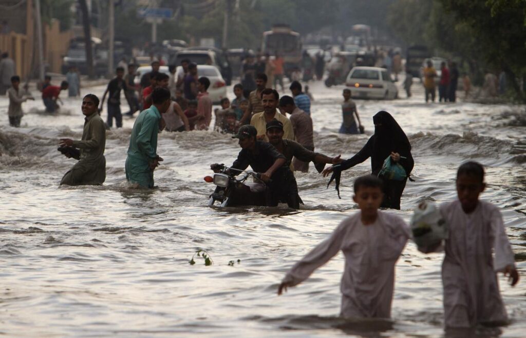
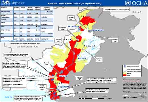

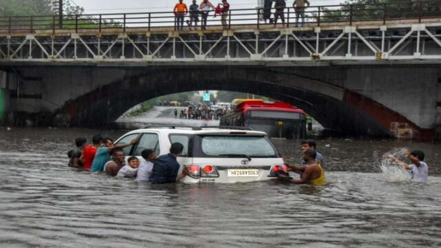
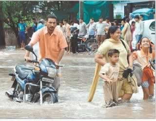

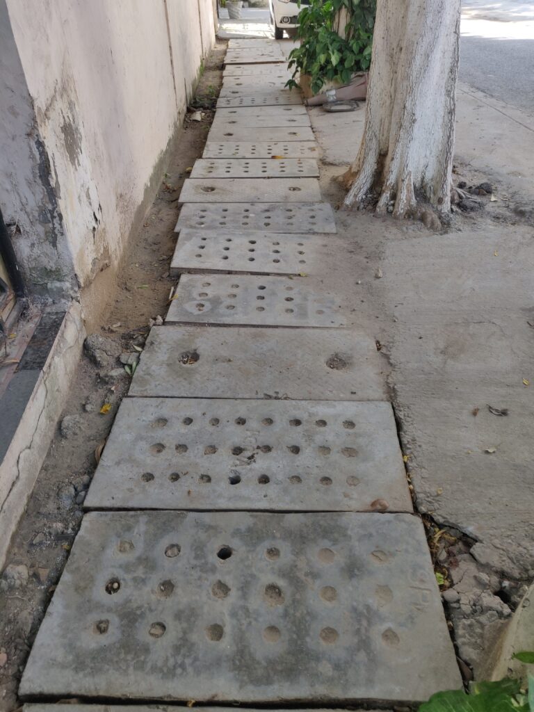
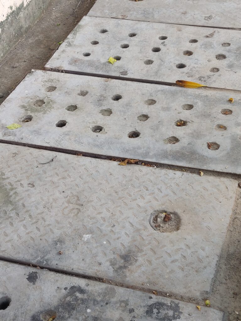
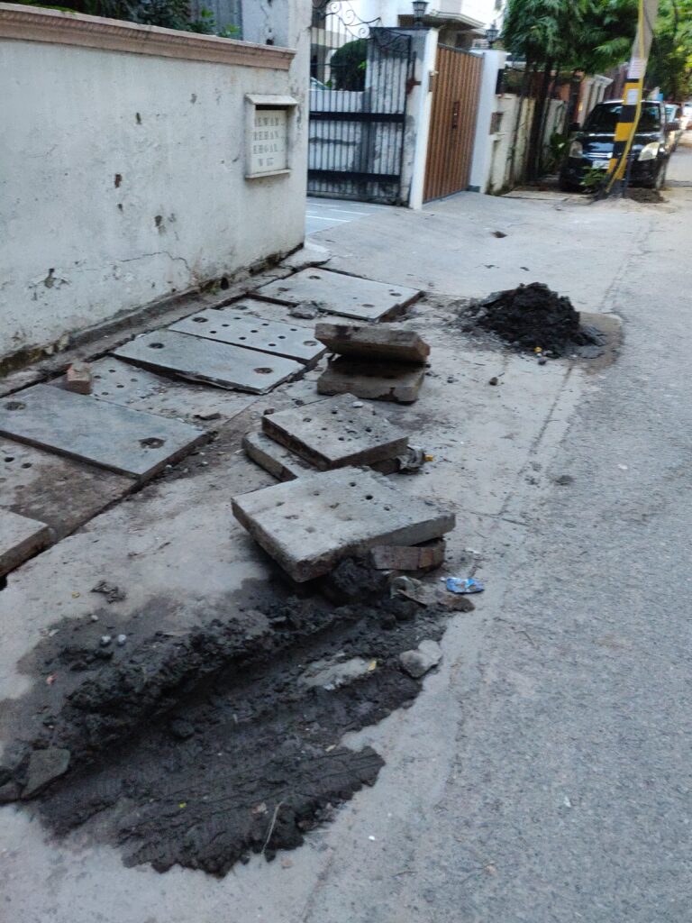
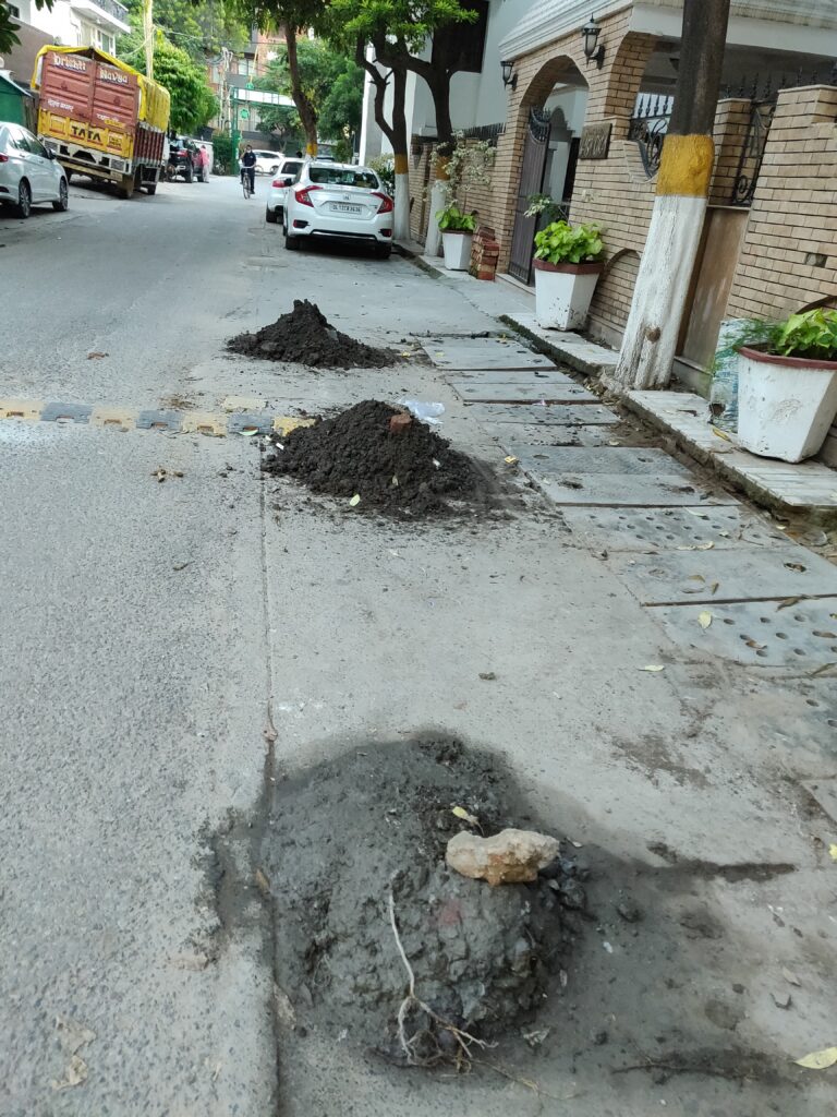


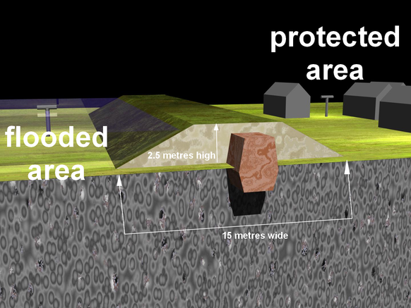

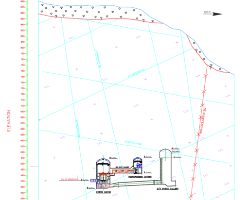
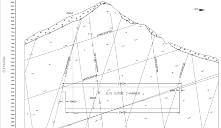
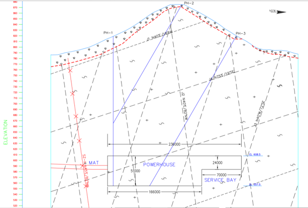
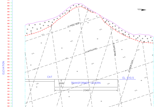
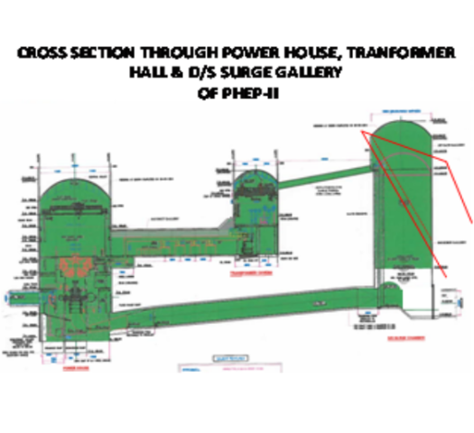
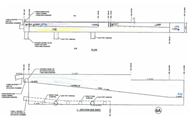
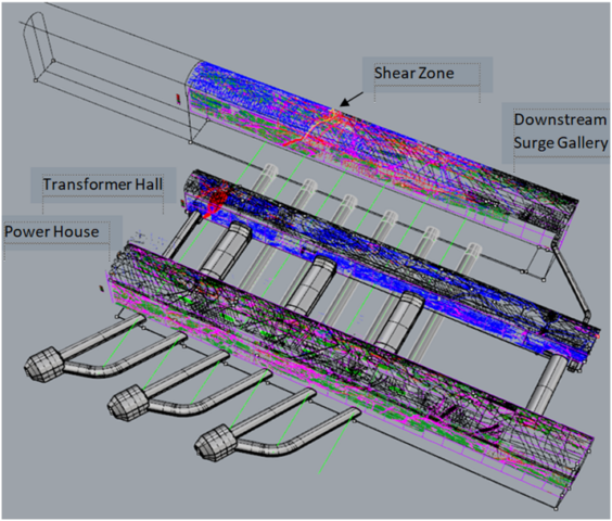
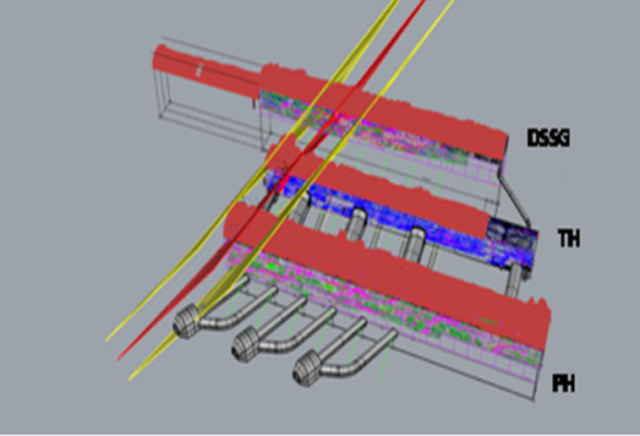
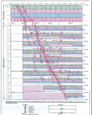
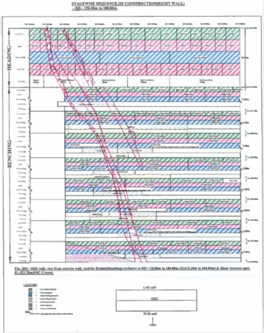
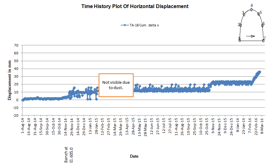
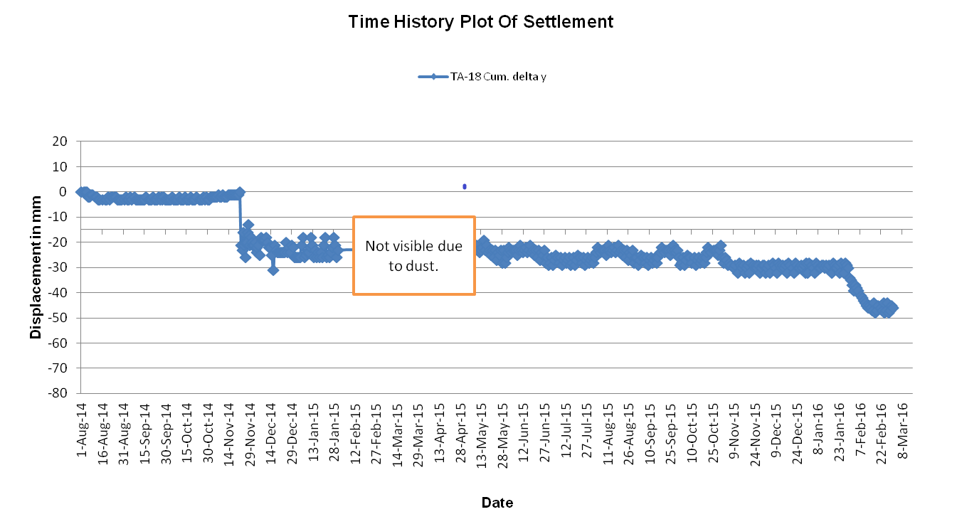
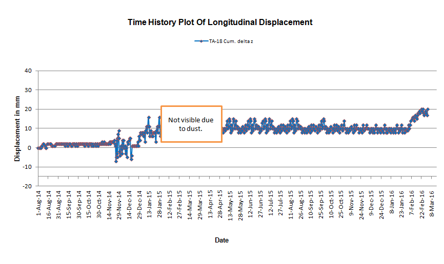
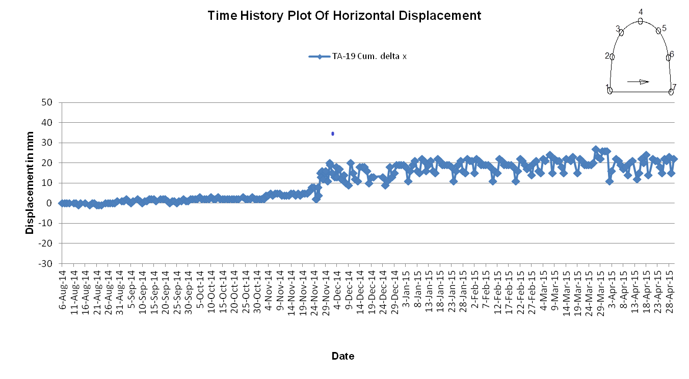
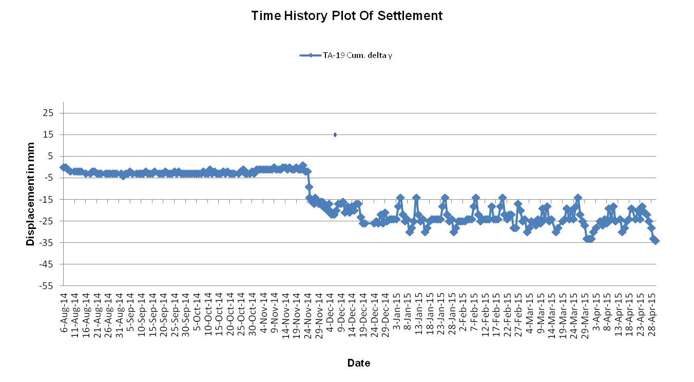
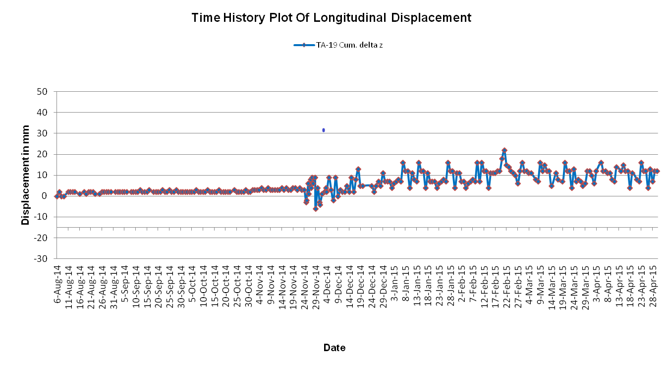
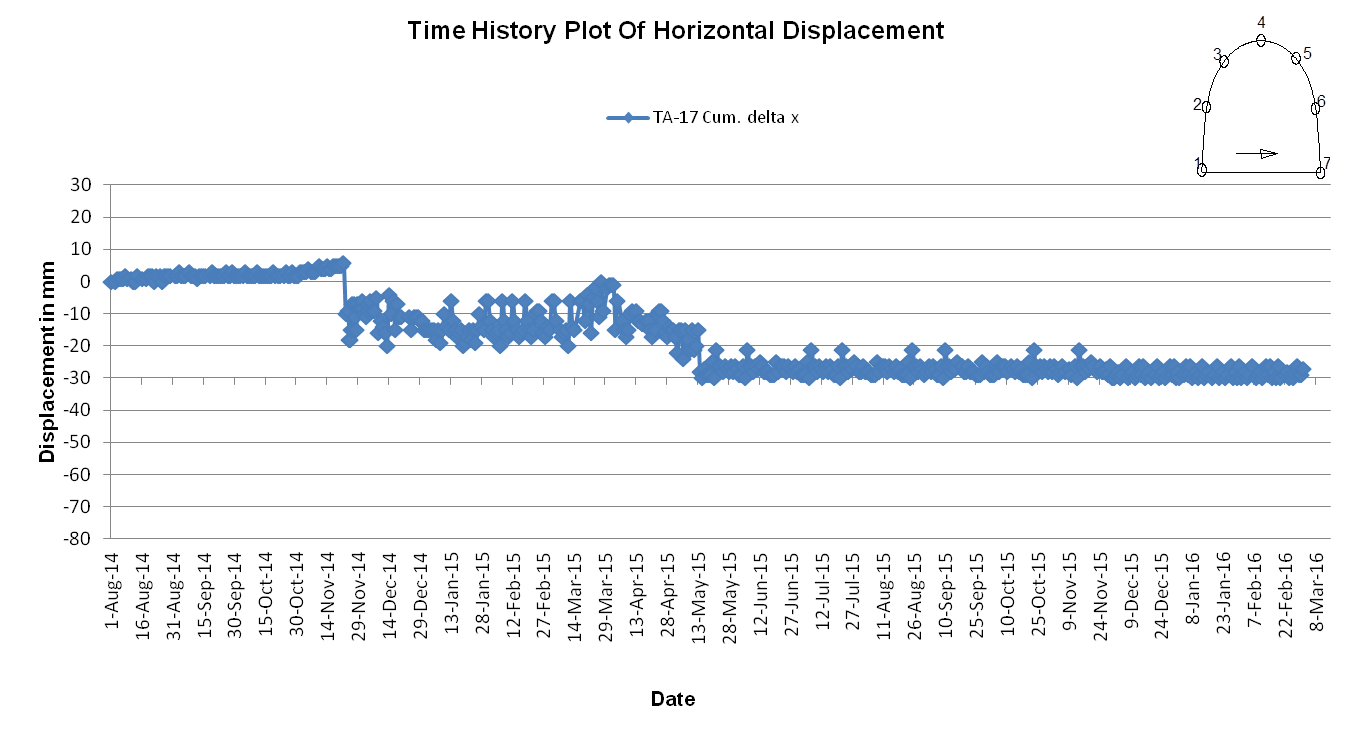
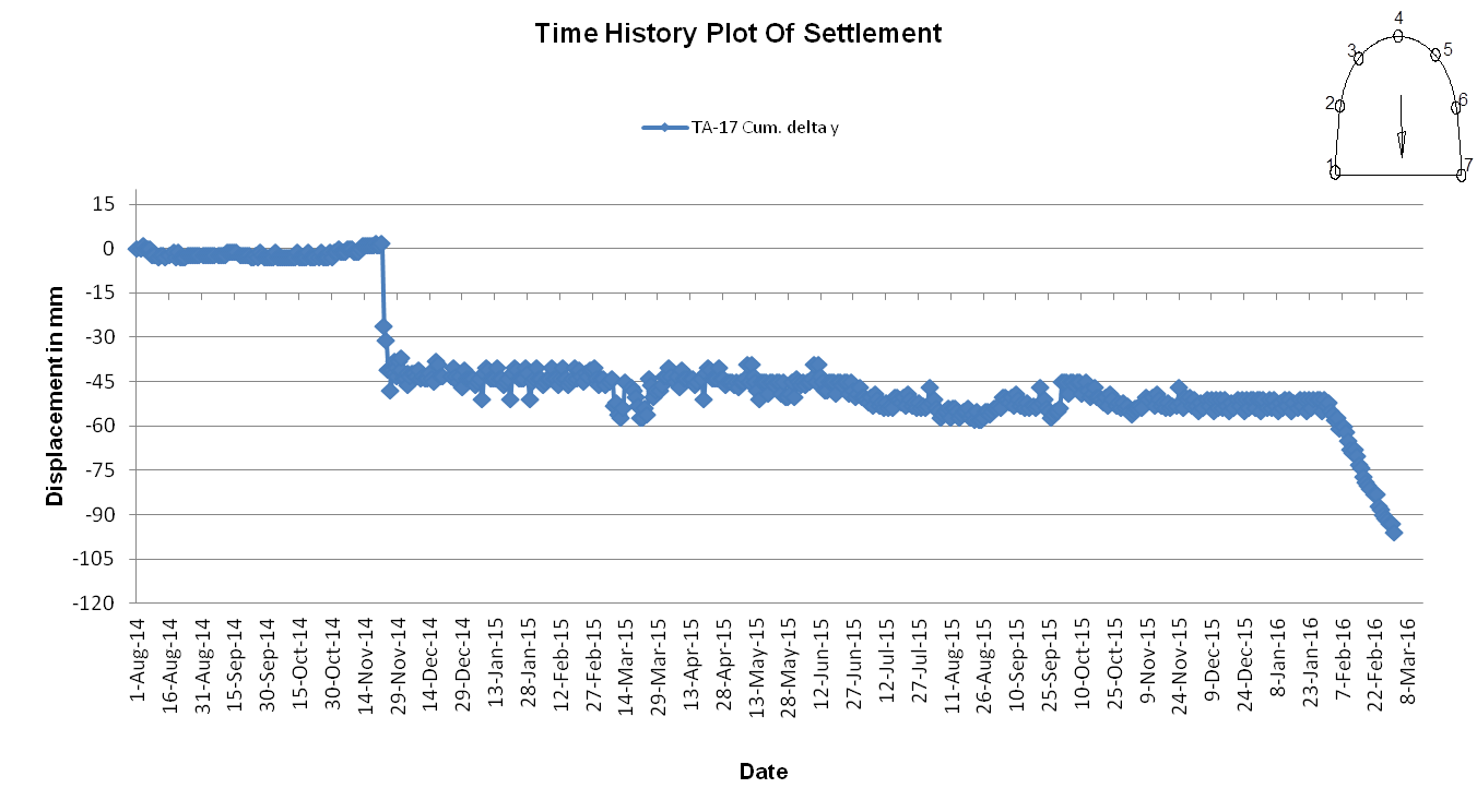
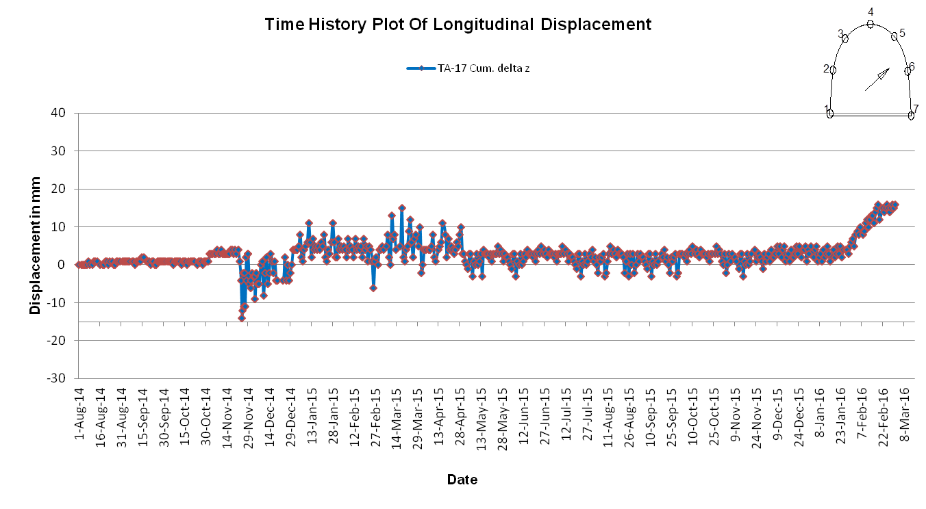
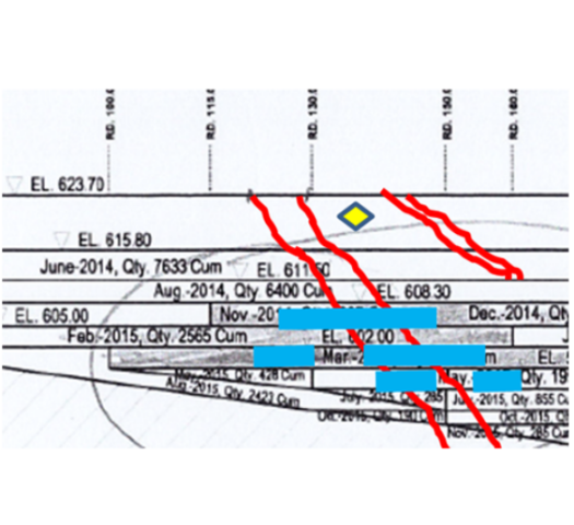
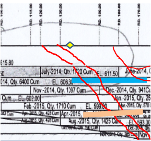
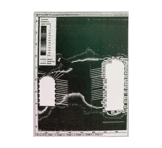
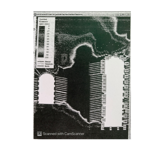
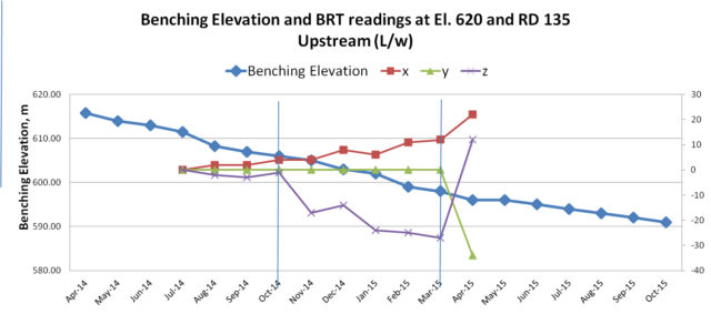
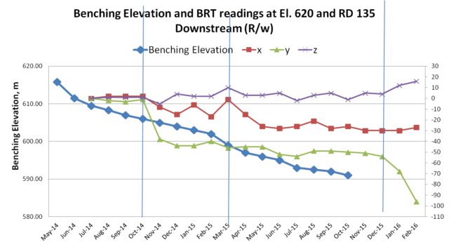
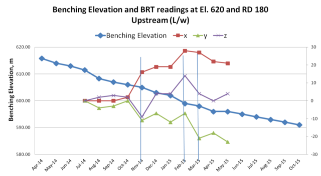
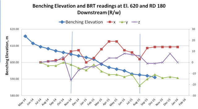
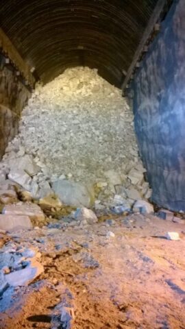
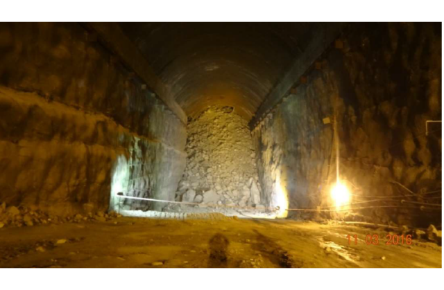
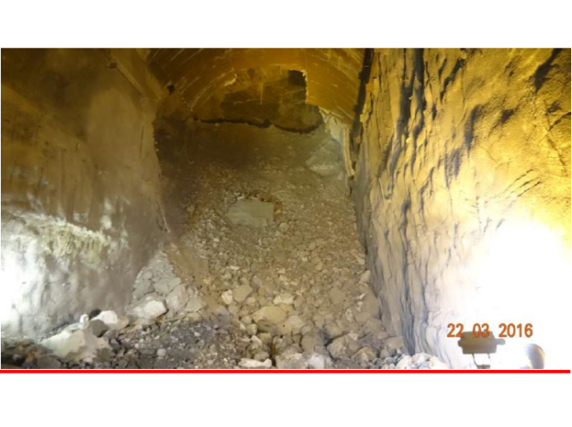
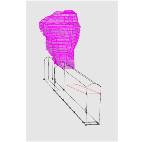
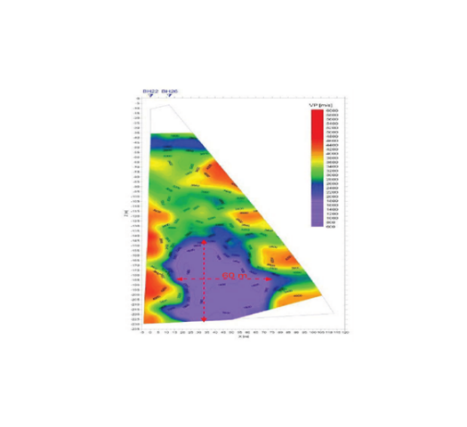


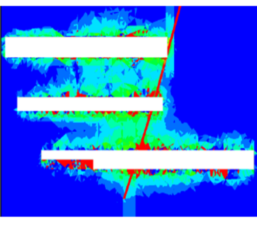
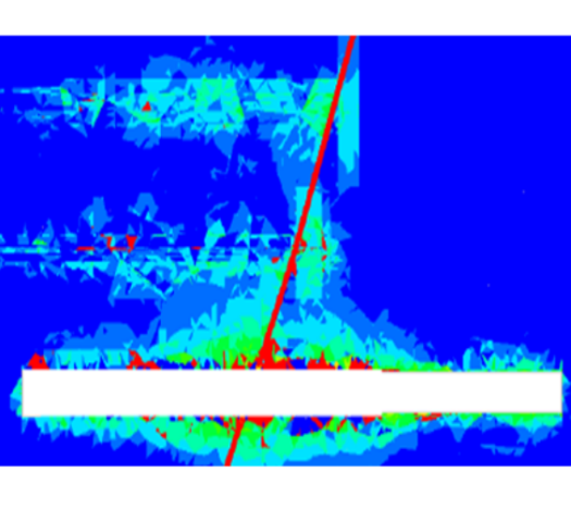

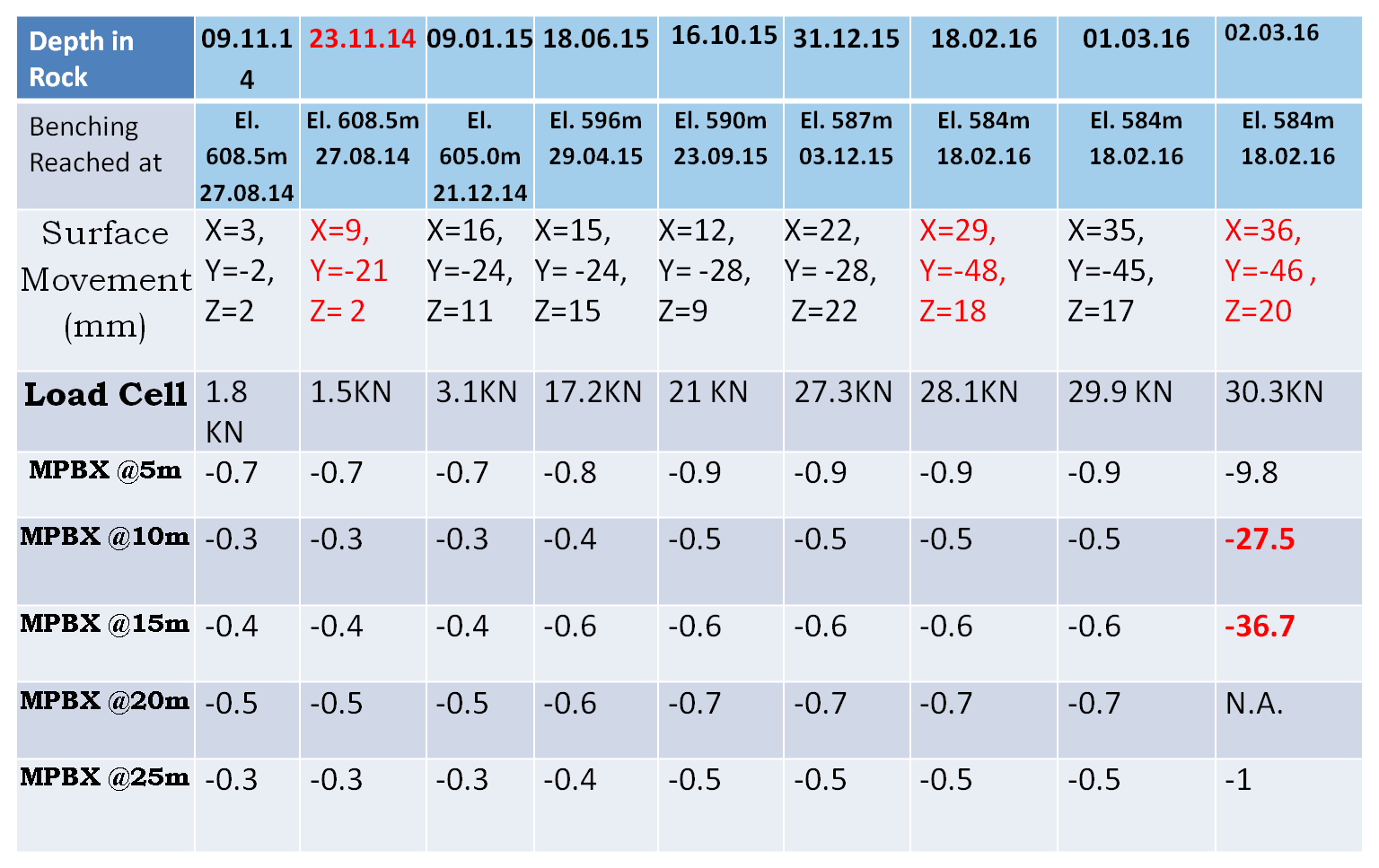
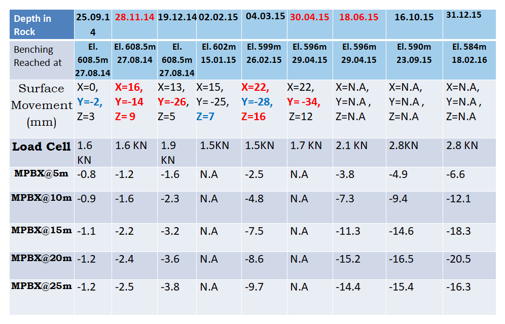
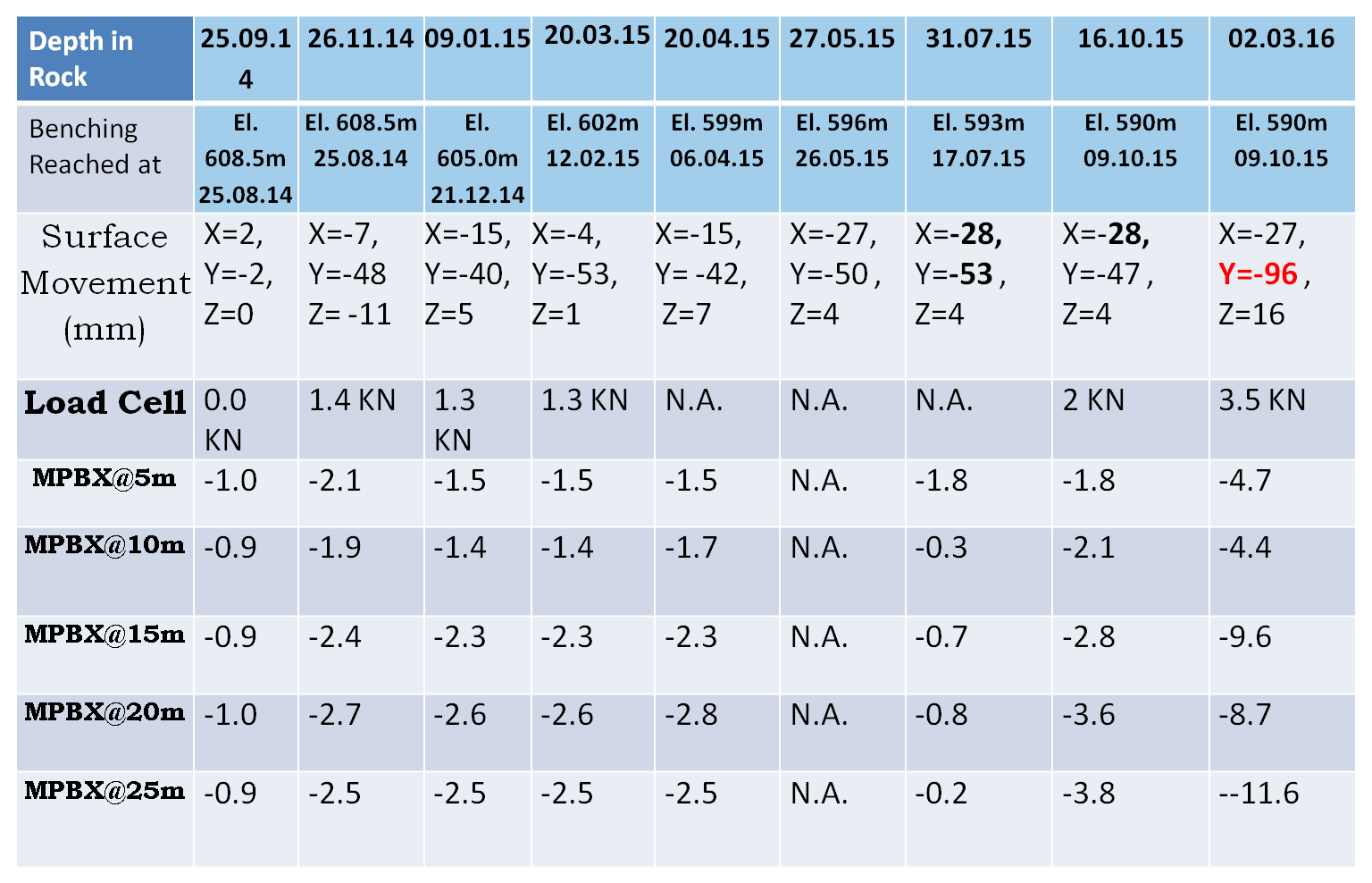
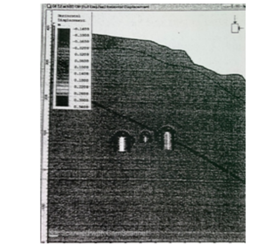
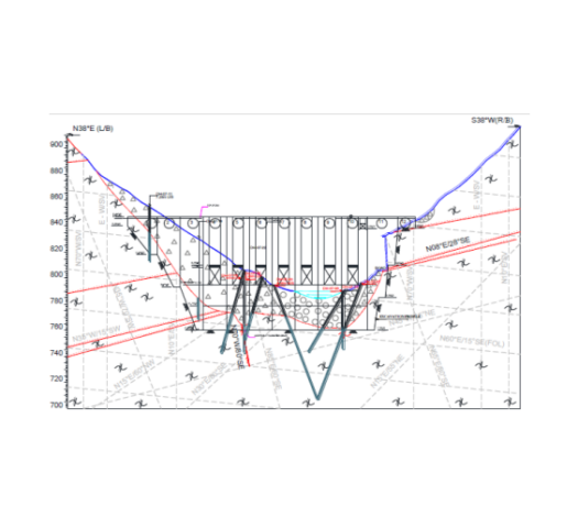
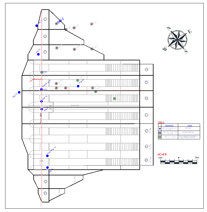
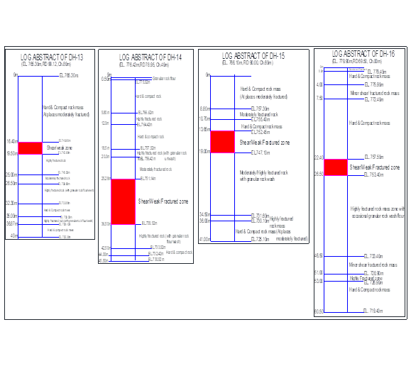
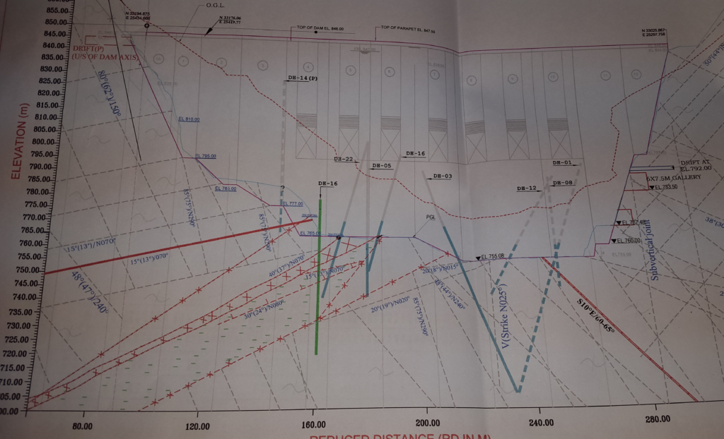
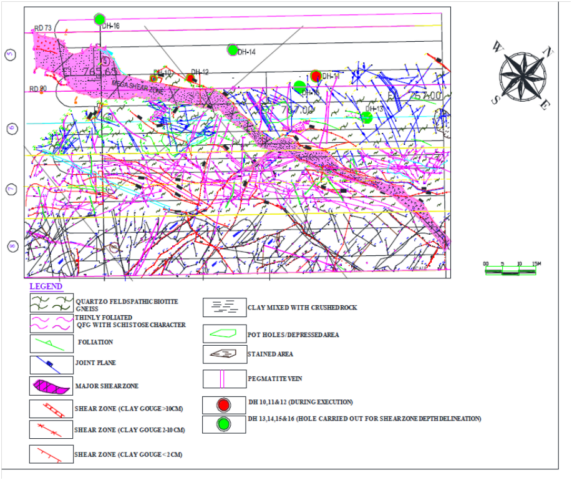
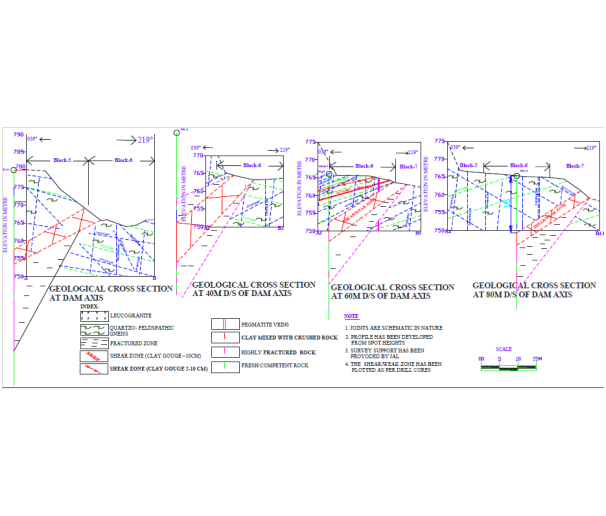
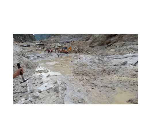
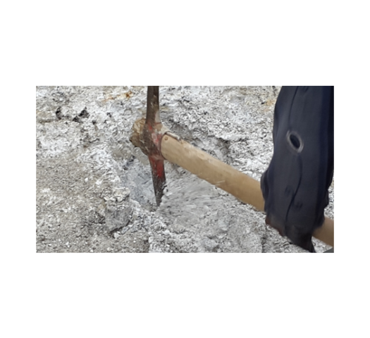
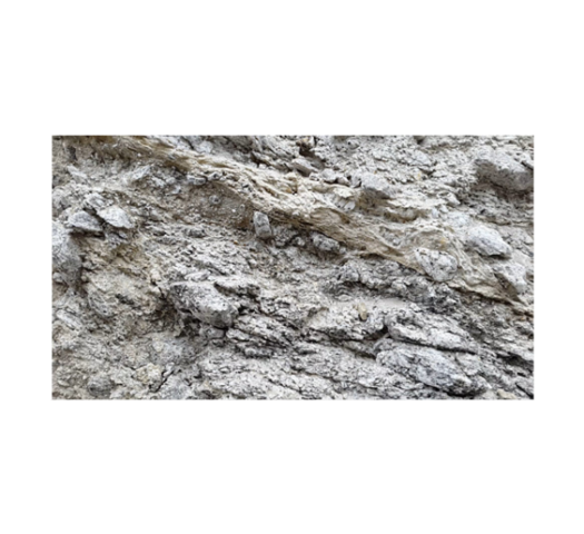
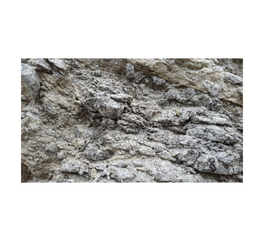
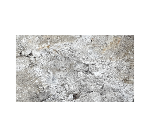

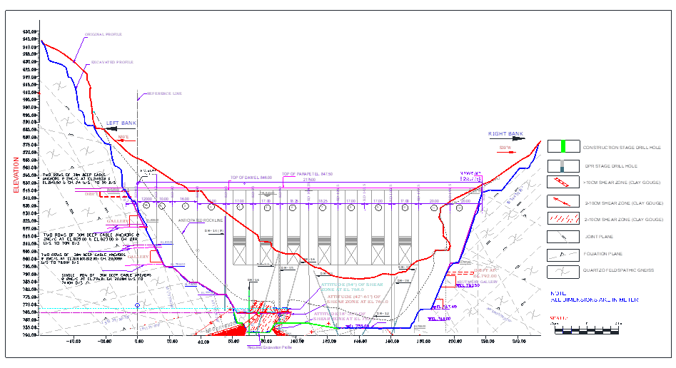
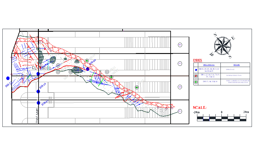
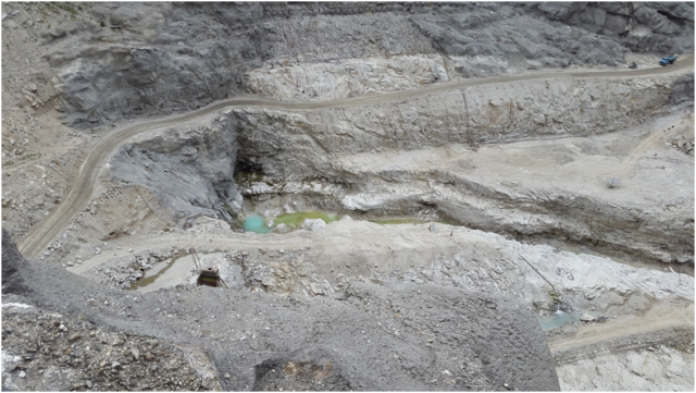
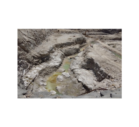
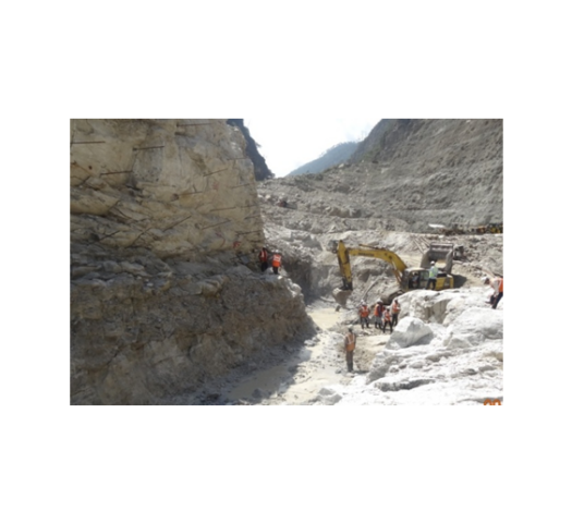
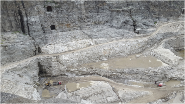
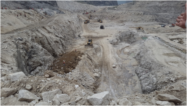
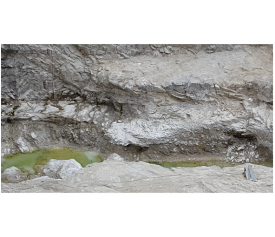
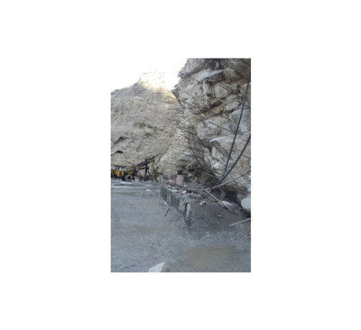
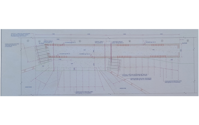
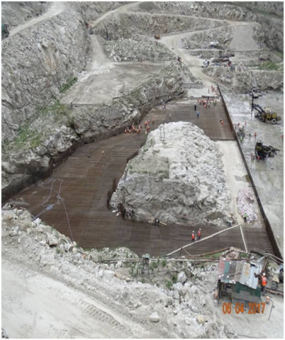

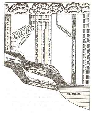