The True Significance of International Day of Yoga / Vivek Atray
While the celebration of the “International Day of Yoga” has become an integral part of the global calendar, especially in India, its true significance lies within our souls.
The inherent meaning of ‘yoga’ or ‘yog’ is ‘union with God’ which is the true union that all souls are innately seeking. Most human beings across the planet have heard of ‘yoga’ but a majority of them still identify this concept with physical exercises or yog-asanas – Hath Yoga. Yet there is so much more to yoga that needs to be understood and practised!
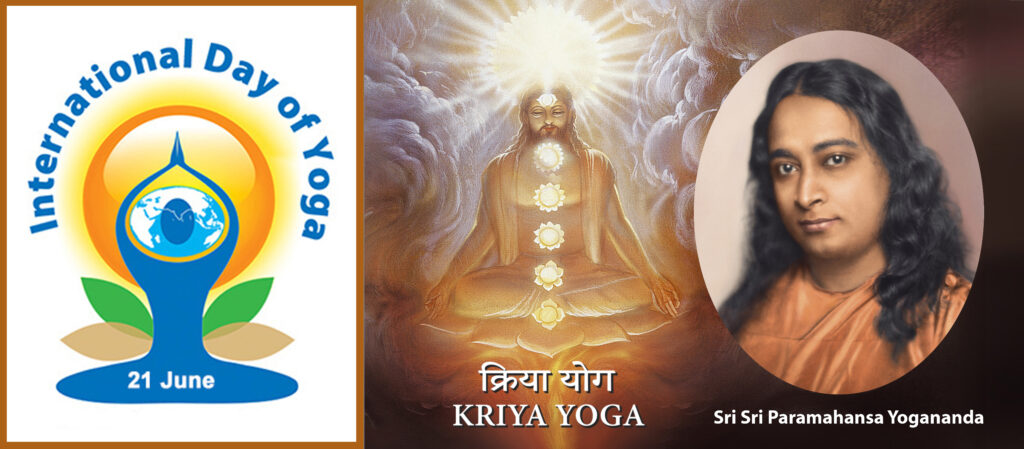
Sri Sri Paramahansa Yogananda, the author of the renowned spiritual classic, “Autobiography of a Yogi” was a pioneering Indian guru who travelled to the western world in order to enlighten truth seekers about the true meaning of yoga. His emphasis on meditation as an integral part of the ‘action plan’ that all individuals must adopt, in their search for the true meaning of life, was timely as well as timeless. Yoganandaji propounded spiritual effort as the only way towards fulfilment of the highest goal of life: self-realization, or oneness with God. And his own guru, Swami Sri Yukteswar Giri, famously said, “Everything in future will improve if you are making a spiritual effort now!”
A step by step scientific technique is what each devotee of God needs to further his or her outreach towards the attainment of the ultimate verities that Yoganandaji writes about in “Autobiography of a Yogi.”
Kriya Yoga is the highest form of yoga and is that specific scientific pathway which Yoganandaji emphasized upon as the foremost route known to mankind for attainment of divine communion. Kriya Yoga involves definite scientific techniques which enable the practitioner to not only improve his or her physical and mental health, but more importantly, it enables the ‘yogi’ to eventually find true peace and joy within which are clear indicators of the presence of God within us.
Yoganandaji explained to his followers, both oriental and western, that the Kriya Yoga path can be practiced by everyone and is a sure shot doorway to the highest realms of existence. He also elaborated upon certain preliminary techniques, as well as a ‘how to live’ philosophy which are essential steps leading to the highest portal of Kriya Yoga meditation. Lord Krishna in the Bhagavad Gita also mentions Kriya Yoga twice in glorious words. Millions have been inspired to adopt Kriya Yoga as a way of life, with all its manifestations. Yet, the real benefit of Kriya Yoga lies in its sincere practice, as Lahiri Mahasaya, guru of Swami Sri Yukteswar Giri, emphasized. The golden gateway to the upper echelons of our existence is to be found in the meaningful and regular practice of the Kriya Yoga technique.
Yogoda Satsanga Society of India (YSS) is the spiritual organization founded in 1917 by Yoganandaji. YSS continues to disseminate deep insights into the voluminous teachings of Yoganandaji, through books, printed lessons and other means. The number of devotees following the Kriya Yoga path have multiplied enormously in recent decades, all over India and the world.
As a young devotee said during a recent ‘Sadhana Sangam’ at the Ranchi Ashram of YSS, “My life has been transformed by the discovery of the teachings of Yoganandaji and the path of Kriya Yoga.” For further info.: yssi.org
Writer: Vivek Atray
Why we should have a healthy lifestyle
By Sunil Sarpal
A healthy lifestyle is a must to lead a life cheerfully.
In the morning before sun rise, visit the close by park for walk/jogging/running as per demands of your age/body. Most of the parks these days have in-built Gym. One can do exercise of your choice. Never miss out on this regimen so that you may start the day in a vibrant and healthy ways.
Consume a coconut milk after the work out.
After a shower, the breakfast should consist of milk and some ‘dry fruits, apart from what you prefer. Avoid Paronthas and too much butter.
Make it a habit not to eat between two meals.
The lunch should always consist of Curd and Salad, apart from Roti, Sabji, Daal, Rice etc. The food should not be spicy and oily.
If because of the demand of your age, you feel like taking a nap, it is your choice.
Tea in the evening accompanied by some biscuits.
Avoid consuming food at dinner time and instead eat fruits, particularly seasonal ones. and hot milk.
Avoid food from outside.
Always eat moderately and never indulge in over eating.
Eat when you feel like and clean up your stomach once or twice in accordance with your routine.
Dont eat non veg and drink liquor. Stay away from the company those prefer such things.
Magical Connects by Neera Nath
We meet people for reasons we don’t know. We connect at so many levels…and yet we may not connect at all. Sometimes we see we’re wearing the same or similar colours, sometimes a friend may simply give us the most enormous bear-hug. How could they know we needed one? Often when I wish for something I get it. This be the power of yoga or meditation. or telepathy heightened by decades of yoga. We can dream of a car and often enough it materialises. Yes, these are also called manifestations or visualizations.
Yes, these are solid tangible facts for some like me who have practised and successfully lived these blessings. It is another way to live to believe emote and exist. So many times, you remember someone only to see the same from them top. I have experienced knowing what a friend needs and for some reason being there and taking care of that need. so many times, when I have been in a low or desired help it has shown up. These are all connects inexplicable but there nevertheless. It is also my quest and desire to live and experience life at another level that has allowed me to experience this. This connecting with another may happen over long distances.
In the coming years these practices will grow. People living in remote areas and forests also practice calling n connecting. They have heightened telepathic skills. All humans have some way these capacities. It suffices to empower and give them life. This connect with a higher energy that may be called by any name begins with connecting with yourself first. The first love affair so to say. I learnt this just a few years back and my god it works. You keep reminding yourself though.
To spend time in silence or with nature or meditate or immerse yourself in a book or music is forms of connection. As also is healing giving loving and spending special moments with loved one’s friends, family, even strangers. I have often potent connects with strangers that Deja-vu feeling, or just some common chord strikes up. If you open yourself to and allow all this to happen – it will. If only people meditated or did some form of it – lives, health – mental or physical, would reach peaks unimaginable. Thus, the world would be happier calmer and perhaps become a utopia
The world now needs a healing touch
Yoga for Wellness
These are the post pandemic times when wellness has become the most spoken, admired, coveted and desired word. Never has the quest for people to feel well, comforted, at ease within themselves, healthy, stress free and especially mentally calm been more flagrant. Years of living in so much unnecessary fear aggravated by an onslaught in the press and media of Covid related over-information have wreaked havoc. Erratic unstable work closures and lack of work, as well as changed work situations, have left millions financial depleted.
Spiritually this translates into accepting and realising that a new beginning, a new reality is taking shape. Our ways of life were no longer sustainable. This itself is a vast subject, but suffice to say that insane working hours and demands as well as many levels of unrealistic living, have suddenly become redundant. Many are questioning their lifestyles.
Recently statistics have shown waves of resignations in Europe and elsewhere and also scores wanting to go back to smaller cities or towns in nature seaside mountains, or living off the grid, or trading their cushy corporate jobs for countryside ones.
Irrespective people want to feel well as they did few years or decades back. They’re willing to make drastic changes in their professional and personal domains just to get there. What matters and what does not are shifting dramatically and many want a balanced harmonious and peaceful living – even if a little divorced from too much technology .
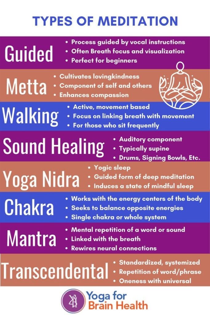
Yoga, meditation, a zillion forms of healing are super fashionable and definitely the trends now. Massages, organic and natural beauty and healing products, Reiki, past life regression and also I know of people practicing Quigong, Taichi and Martial Arts to balance out . There will definitely be an enormous resurgence of all forms of healing in the coming years. It is the need of the hour and many more shall succumb to their magical mystical healing.
Image Courtesy: Yoga for Brain Health
Nature’s Aura In Your Home
As I sit with the cool morning breezes wafting across from my organic, a little over grown and lush, full garden; I cannot help wonder why most people cannot and have not allowed greenery to fill their lives and spaces.
There is zero pollution in my home although I am situated next to and in a polluted area. My back lane has tall trees and a multitude of beautiful floral creepers whose aroma fills me when I open my windows. Everyone yes everyone can grow greens in gardens, terraces, pots, tubs and containers, recycled Pots, hanging baskets and now even hydroponics.
There are homes laden with green walls where owners have banished any negative air with plants as well as magically transformed their interiors, also terraces overflowing with vegetation and blocking off unseemly adjacent buildings and kitchen gardens, in soil or in pots or even wooden crates where families can joyfully harvest their vegetable and herb requirements.
Those with space do multi-cropping, fruiting trees, crops and afore mentioned herbs and vegetables. Many terraces are filled with cascading creepers as well as so many stunning indoor plants. These are not at all complicated to grow.
Just love and a little effort and the intent to transform your space health and life. Layering and also placing plants at various levels and creating green walls are really a very contemporary fashionable interior trends.
Either way its a win win. Just a beautiful tree surrounded by ground cover or trailing plants and florals can be a master centre-piece, or surrounded by pots or a raised bed to sit.
As a designer I view all from the aesthetic or beauty point of view. Yes practicalities go hand in hand. But its so easy to beautify and energize your environment. Its also important not to have only the passé notion of over cut manicured gardens.
Let plants proliferate. They sing their song . Make your compost, use cut grass and fallen dry and green leaves to fill your beds to act as mulch. Not only would it look like a natural forest bed but would work wonders for all plants as well as reduce tremendously the water needs.The future will require us all to rethink about what we grow and how we cultivate. I would love to see more perennial lush and natural gardens or terraces filled with plants flowers that fill all our lives.
Give your feedback or share your experiences in the comment box below
LIFE IN A STATIC BUILDING
HETAL SHAH [Teacher] ARVINDBHAI PATEL INSTITUTE OF ENVIRONMENTAL DESIGN (APIED), V.V.NAGER GUJARAT, INDIA
“When a building is being built there is an impatience to bring it into being. Not a blade of the grass can grow near this activity. Look at the building after it is built. each part that was built with so much anxiety, joy and willingness to proceed, tries to say when you are using the building, ”let me tell you about how I was made” nobody is listening because the building is now satisfying need. The desire in its making is not evident. as, time passes when it is ruin, the spirit of its making comes back, it welcomes the foliage that intervenes and conceals. Everyone who passes can hear the story it wants to tell about its making. It is no longer in servitude; the spirit is back.” – Louis kahn
Images Courtesy: See Below
I have witnessed the pre-birth stage of the building, taking shape in the earth’s womb. digging the earth for foundation, JCB machine moving inside the depth of the earth, carving moment by moment the void for giving immense strength to the structure; tying of the string and drawing of the guideline for foundation in the void seems to me a womb is thickening its lining to embed embryo. Those commotional preparations, assembling of huge machines and stacking of material are as if mother earth is strengthening her to hold baby inside. Slowly but steadily erecting foundation column look like anatomical blueprint. If a human skin and buildings design are stripped down, there would be the same overlapping layer of muscles and materials almost at the same place. Those rose up foundation columns’, taking firm grip in the soil seems like supporting spinal cords. then pits are filled up by mechanical arms, scattering soil over foundation columns are slowly-slowly depth vanishes, only steel bars are left on the re-leveled ground which looks like ”umbilical cord” connecting to the mother’s womb, ensuring fetus for support.
day by day going on construction, scaffolding with a central spines of columns, skeleton of beams, layer upon layer of material, like muscles hiding bony structure in human body, which forming solid flesh beneath the skin. Various structural joints allow this remarkable construction to move with great versatility. The building blocks and brickwork between columns and beams are likes a cartilage giving shape and support. The running grooves on the walls for concealed electrification are the nervous system and, wide and narrow plumbing pipelines are like digestive system of the building.
The complete silence hidden in the darkness that spreads through the height of the stair shaft connects the navel of the building to the depth of the foundation. That height can measure the scale of the depth within no time. It strengthens the experience of vertical dimension of the building, at the same time make us aware about immense depth of the earth. It levitates our dream and provides them flight.
The weary laborer who works in the bare footed in the scorching heat of the sun, their skilled\scaled hands rhythmically taking stones from the mutually piled rows and carrying loads on their heads seems a mother struggling hard to bring up her beloved child. At the end of hectic day when laborers sprinkle water to construction, thirsty walls are swigging, the patterns formed by it are like a joyful games of reflection on the surface. What a divine feeling to observe void taking shape! Architecture presents the drama of construction silenced into the matter, shape and light. When the clutter of construction work ceases and shouting of workers dies away, a building becomes a museum of waiting patience and silence!!
The absent minded gage doors and windows penetrates the surface of the physical image like wall and focus in infinity. Building starts breathing through the opening. What interests mean about its transparency is the idea of evaporation. Transparency is also TRANS-APPEARANCE. The building is now sensing the world. It makes the world aware about its being. The geometry of thoughts echoes the geometry of the room. Architecture is deeply engaged in the metaphysical question of the self and the world, inwardness and outwardness, time and duration, life and death. Why do abandoned houses always have the same hollow smell??? Is it because the particular smell is stimulated by emptiness observed by the eyes???
The body’s first line of defense against the possible damage is the skin, which provides a protective barrier between our environment and us. Now it is a time to surface out the building. The tactile sense connects us with the time and tradition; through impression of touch, we shake the hands of countless generation. A stone polished by its usage is pleasurable to touch, it expresses the slow process of the formation, it is time turned into shape. We trace the density and texture of the ground through our soles. One senses the slow breathing of the floor. Stokes writes, ” I should like to eat up this verona marble touch by touch”.
In our houses, we have nooks and corners in which we like to curl up comfortably. To curl up belongs to the phenomenology of the verb to inhabit and only those who have learnt to do so can inhabit with intensity and always in a daydream, the house is the mother womb or a large cradle. I remember even today nostalgic moments of my sweet childhood, when I licked the age of parapet on the terrace and felt a human touch by running finger on door handle of my room. I never have such sound sleep, which I got in childhood while listening music of torrential rain on the roof. I used to be lost in that music for limitless hours.
We have yet not designed the building to end all building; we haven’t yet created the city to end all cities or a thought to end all thoughts. So, as long as this utopia remains non-materialized there is hoping to go on. Architecture is always hiding behind drawstrings, behind words, behind percepts, behind habits, behind technical constraints. There is no way to perform Architecture in a book. Words and drawings can only produce paper space and not the experience of real space, where meaning is derived from the order of experience rather than the order of composition. Architecture cannot be taught, are learnt, it is a passion to be persuaded and achieve. It is the creativity which has brought man closer to the God, the ultimate creator (which is just an Imagination – Hoax)…!!
References
1. The eyes of the skin _ Book by Juhani Pallasmaa
2. The Thinking Hand: Existential and Embodied Wisdom_Book by Juhani Pallasmaa
3. Complexity and contradiction in architecture_ book by Robert Venturi
4. Thinking architecture_ book by Peter Zumthor
5. Space as a Membrane _ Book by Siegfried ebeling
6. Atmospheres _ Book by Peter Zumthor
IMAGES COURTESY: 1. Ar. Umang Goswami, UA Design, Ahmedabad
Can Pacifists like Modi and Macron help to nudge the world towards peace?
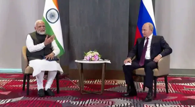
War helps no one on this planet – specially not the people, plants and all living beings who inhabit it. One Vorld One Universe One Mankind is the guiding principle, which will help resolve all issues. One would like to promote world peace, but with dignity for all and without compromise to extremism. There are hardly any who talk about peace in the present scenario in Europe. However two leaders who stand out and are proactive about peace are undoubtedly Modi and Macron. PM Modi’s role came into limelight during SCO summit, but ever since war began he has been talking about peace privately to Putin and also Zelensky. On the other hand President Macron met President Putin in Moscow, way back in February 2022 aiming for a de-escalation.
Prime Minister Narendra Modi’s advice to Russian President Vladimir Putin over the Ukraine war during a bilateral meeting on the sidelines of the Shanghai Cooperation Organization (SCO) summit at Samarkand in Uzbekistan has created hopes that perhaps it might be a catalyst to the end of Russia-Ukraine war. While his intervention has received approval from the world leaders, it has also grabbed the attention of leading international press and media
Japanese publication, NHK headlined “Indian PM Modi tells Putin to pursue peace”, Even Chinese media approved of it as the Hong Kong-based l South China Morning Post reported: Now is ‘not a time for war’, India’s Modi tells Russia’s Putin who agrees to ‘end this as soon as possible.’
Politico from US reported; “India’s Modi tells Putin: This is ‘not the era for war” and US News headlines was “Indian PM Modi Tells Russia’s Putin Now ‘Is Not an Era of War”.
On Internationally telecast media, while expressing his concerns about the impact of the war on food and energy security, PM Modi told Putin, “Today’s era is not of war and I have spoken to you about it on the call. Today we will get the opportunity to talk about how we can progress on the path of peace. India and Russia have stayed together with each other for several decades,”
“We spoke several times on the phone about India-Russia bilateral relations and various issues. We should find ways to address the problems of food, fuel security and fertilizers. I want to thank Russia and Ukraine for helping us to evacuate our students from Ukraine,” the Prime Minister added.
International media appreciated PM Modi’s diplomatic tact, who in a friendly manner pushed the concerns of the world at large to its long-standing friend Russia.
CNN appreciated PM Modi’s understanding of the situation and reported ” Indian leader Narendra Modi tells Putin: Now is not the time for war”
Washington Post, headlined “Modi rebukes Putin over war in Ukraine”.
“India’s Leader Tells Putin That Now Is Not an Era for War,” The New York Times said in its headline
Following the SCO summit, India’s role as a peace maker was applauded at the 77th UN General Assembly by world leaders. French President Emmanuel Macron proclaimed that Indian PM Modi was right when he said that time is not for war, not for revenge against the west or for opposing the west against east. It is time for our sovereign equal states to cope together with challenges we face: . German envoy quipped “very well put” to PM Modis remark on the Russia Ukraine conflict. US National Security Advisor Jake Sullivan cited Modi’s remark urging Putin to end the war. Other world leaders like Ukrainian President, Volodymyr Zelensky , Russian Foreign Minister Sergey Lavrov,also cited Modi’s advice in their speeches. Indian External Affairs Minister summarized; “I am concluding this week with the sense that India really matters more in this polarised world and much of that is also due to the Prime Minister’s leadership, his image, what he has done on the global stage,”
PM Modi also had a telephonic conversation with Ukrainian President Volodymyr Zelensky wherein as per official sources, he conveyed India’s readiness to contribute to any peace efforts in the Russia-Ukraine crisis. he stated that there can be no military solution to the conflict and reiterated his call for early cessation of hostilities and the need to pursue the path of dialogue and diplomacy..
Unlike India, France did not take a neutral stand at UN and voted against Russia in the security council. Yet even before PM Modi’s advice to President Putin Macron has been advocating a reconciliatory approach. As reported by world media, including EuroNews
As far back as May 2022, French President Emmanuel Macron has warned against humiliating Russia for its invasion of Ukraine, if and when any peace settlement is agreed.
He told reporters in Strasbourg that once the war ends, Moscow and Kyiv will eventually have to sit down and negotiate with each other, so any further tensions will only serve to the detriment of the situation.
“We will have a peace to build tomorrow, let us never forget that,” Macron said on Monday. “I mentioned this earlier. We will have to do this with Ukraine and Russia around the table. The end of the discussion and the negotiation will be set by Ukraine and Russia. But it will not be done in denial, nor in exclusion of each other, nor even in humiliation.”
Macron also laid out his vision of a broader community of European democracies that would allow for deeper cooperation between non-EU countries. (EuroNews 9th May)
Even earlier on February 7, 2022 NY Times headline news was “Macron meets Putin in Moscow, aiming for a de-escalation”. It went on to add “President Emmanuel Macron of France, who has positioned himself at the center of Europe’s furious diplomatic maneuvering over Ukraine, said on Monday that the continent was at a “critical crossroads” as he met in Moscow with President Vladimir V. Putin of Russia”..However there were murmurs of disapproval by some other countries watch the vido below to get both sided of the story.
Our Columnist Sunil Sarpal recalls the recent background to this war.
The war between USSR and Ukrain broke out approx. 6 months ago. The cause of disenchantment was that USSR did not want Ukrain joining NATO. USSR feared that if Ukrain, whose border separates the two nations, join NATO, other NATO affiliated nations’ forces could line up Ukrain border and intimidate USSR. As of now, the situation has unfolded that 20% Ukrain territory is under USSR control and the war goes on unabated. The devastation took place because of the war is unprecedented.
Is Zelenskey responsible for the war or Putin ?
Putin’s invasion of Ukrain proved a total miscalculation. As days progressed, it seems that the war will go on and on. Because Ukrain forces retaliated in such a manner that USSR forces ran away from the warring zone, leaving behind tanks, arma and others weapons in order to save their lives.
On both sides, the loss of lives and infrastructure took place as never before.
When war broke out an assurance came from none other than USA to Ukrain that they are whole-heartedly behind them, but USA never sent his forces to Ukrain. Of course, sanctions and war-related weapons etc have been supplied by them as well as by Germany. The fear factor on the part of USA could be that if their forces join hands with Ukrain, it would turn out to be a world war.
If Ukrain President Zelenskey is so very stubborn to prolong the war and asking for help from USA and other nations, then Ukrain inviting more trouble. The complete devastation of Ukrain could be averted if Zelenskey relents to Putin’s stand. On the face of USSR might, Ukrain’s defeat is on the cards whatever or how much coming their way.
In this war, both Putin and Zelenskey are held responsible because of their respective stands. Attempts have been made to kill both Putin and Zelenskey separately thru bombs but both escaped unscathed.
But will the momentum for peace, proposed by pacifists like Modi and Macron, gather pace or will temporary victories or setbacks of either side stall the move towards détente, remains to be seen – Manohar Khushalani.
Creating recovery resources in mental health – 1
This is a first of what may be a set of posts around the same theme- recovery in mental health or recovery from mental health issues, regaining one’s sense of wellbeing after an emotional/psychological setback.
The past year has gone in a lot of work in this area (also among the reasons I could not write on this blog). So now is the time to talk about the work which has been done away from the public eye.
Let me begin with the book, which comes out later this year, I put to bed a few months ago. Currently the last phase of that is underway- on the production front.
As an aside, a somewhat disconcerting thought which has always been there at the back of my head is that when we say the word ‘recovery’ in the context of mental health it conjures a particular kind of image. Recovery is often mistaken to be the recognition of someone’s suffering as a diagnostic reality. (Oh, but this was not the disconcerting thought I had in mind- it was about my book and how academic it is!)
“Oh, now I know why I was feeling so bad. I have anxiety after all“.
“I got a diagnosis of PTSD and chronic depression. I was also wondering what is going wrong.”
This description of suffering and its reframing into a diagnostic “truth” is what happens all the time in the field of mental health, something that troubles me immensely. But I will not go into that trouble right now. I better share with you what is the problem for me to solve here- the problem of talking about recovery.
I recovered from bipolar disorder. It may sound like something un-relatable, for one is not supposed to. In other words I am an outlier by all standards. This sudden disclosure is not part of my identity politics and I do not use mental health as a means for attention-seeking for I am troubled by it. For me my positioning is an ethical stance which comes with an agenda, largely research driven.
My agenda
My agenda post my own recovery was twosome. First it became to map my own recovery- for how did I recover?
I had no clear cut ways to share with another. I am talking about the year 2011. That was the time I started on recovery research, and a number of articles followed in diverse journals across the globe- Psychological Studies, Canadian Journal of Music Therapy, World Cultural Psychiatry Research Review and others (you are welcome to check them from my linkedin profile, ResearchGate or Academia networks. Oh yes, there is one article which is just a click away in which you can both read my (less academic) writing and hear my (self composed) songs (ghazals to be more precise). A longer piece of writing about the ghazal and its role in my healing is there in the World Cultural Psychiatry Research Review (2015).
My second agenda is/was to see if one person can recover, why are others not able to. Or rather, what is it that does not allow more people to recover- which became my PhD research (2016-2020)
Three decades in the field and five decades of life behind me, I know there was none other than this which was my goal, at least for now- recovery research. So while the research was done as a PhD and barriers to recovery found the next and more befuddling (may I say unenviable) option is how to tell others they can recover as well?
This is what I am doing nowadays- creating those other resources to disseminate the findings from my work, advocacy about recovery from mental health issues and suchlike things.
I am not going to say further in this post except having introduced the context- of who I am, where I come from and why I talk about recovery so much. And yes the resources I am busy creating- resources for recovery, advocacy and helping others recover just as well as me.
The first put to bed was the book of course. I will talk about it closer to the time it publishes (later this year)
The second is DIALOGUES FOR RECOVERY with the support and handholding by Vidya Sagar, Chennai. Here is a sample of that work, though we are not yet adept with this sort of work. Whatever else is unfolding is still firming up and I will share about them in subsequent posts. But I invite you to read the writing I have shared, which are scores of articles about my recovery and where I stand today, or what ideas I propagate via diverse means. The video that follows is a sample. There are at least five others of its siblings you can check from the same link and you get to hear my other ideas too (not mine solely, of course for we all stand on the shoulders of giants after all) …
One of six parts of a single discussion between Prateeksha Sharma, Bright Side Family Counseling Center and Poonam Natarajan, Vidya Sagar, Chennai
Understanding Oxygen Concentrators
Everyone is talking about oxygen concentrators now. Most of us had not heard of them before. Many know about distillers which extract water from air, yet very few realised that even oxygen can be extracted from air. So what is an Oxygen Concentrator and how do you choose the right one?
The most important is to understand that Covid patients require 90% Oxygen concentration at 1to 5Litre flow and above to 10L
Tips on Selecting the right oxygen concentrator.
The most important is to understand Covid patients require 90% Oxygen concentration at 1to 5Litre flow and above to 10L when they are suffering with acute respiratory discomfort.
90% oxygen concentration is the most important point here.
We can break down oxygen concentrator into small (5 to 10 kg) oxygen concentrator suitable for COPD patients, medium (15 to 19kg) and large (20kg and above) oxygen concentrators are suitable for critical care and for COVID patients.
Small oxygen concentrators can have options from 1 Litre to 9 Litre Flow but this does not mean you get 90% oxygen at higher flow like at 5 litre. On small oxygen concentrators 90% oxygen contration is achieved only at lower flows of 1litre to 2 litre. on higher flows the oxygen concentration drops to 30% as you increase the flow. Suitable for COPD patients but not for COVID patients.
Check the specs of the oxygen concentrator and if you see 90% – 30% or ( 1L/min , 2L/min) means 90% oxygen is available only at 1Litre flow or 2Litre flow respectively and on higher flows oxygen drops to 30%. The air we breathing is with 29% oxygen. So small (5kg to 10kg ) oxygen concentrator at higher flows gives output of 30% oxygen means its just blowing air.
weight is the best indicator to understand the oxygen production capacity.
A 5kg to 10kg oxygen concentrator means a small compressor which will only mange to give an output of 90% oxygen at 1 litre to max 2 Litre
A 15kg to 19kg Oxygen Concentrator will have a compressor that can easily give an output of 90% oxygen at flows from 1 Litre to 5 Litre Oxygen (Ideal for COVID patients and critical care patients)
A 20 kg and above oxygen concentrator will have a large compressor which can give an output of 90% oxygen from 1Litre to 10Litre flow. (Ideal for COVID patients and critical care patients and for dual patients to use same machine with accessories)
Please do not only see the output flow of an oxygen concentrator like 5litre, 10litre or so. the most important is to make sure you get 90% Oxygen at highest flow level.
For a small family with no senior citizens a 5 litre at 90% oxygen concentration should be good enough.
For 2 senior citizens or for a big family 10 litre at 90% oxygen concentration should be good enough as it can support 2 patients at once if the need arises. And can assist senior citizens during home critical care if the need arises.
Please do not get fooled and pay big money for small oxygen concentrator sold by highlighting 5 Litre and 8 Litre and do not give an output of 90% concentration of oxygen at higher flows which is the need of the hour.
Please read the specs well and if required please ask your supplier to show you the oxygen output on an oxygen analyzer at higher flow of 5 Litre or 10 Litre.
they are suffering with acute respiratory discomfort.
90% oxygen concentration is the most important point here.
We can break down oxygen concentrator into small (5 to 10 kg) oxygen concentrator suitable for COPD patients, medium (15 to 19kg) and large (20kg and above) oxygen concentrators are suitable for critical care and for COVID patients.
Small oxygen concentrators can have options from 1 Litre to 9 Litre Flow but this does not mean you get 90% oxygen at higher flow like at 5 litre. On small oxygen concentrators 90% oxygen contration is achieved only at lower flows of 1litre to 2 litre. on higher flows the oxygen concentration drops to 30% as you increase the flow. Suitable for COPD patients but not for COVID patients.
Check the specs of the oxygen concentrator and if you see 90% – 30% or ( 1L/min , 2L/min) means 90% oxygen is available only at 1Litre flow or 2Litre flow respectively and on higher flows oxygen drops to 30%. The air we breathing is with 29% oxygen. So small (5kg to 10kg ) oxygen concentrator at higher flows gives output of 30% oxygen means its just blowing air.
weight is the best indicator to understand the oxygen production capacity.
A 5kg to 10kg oxygen concentrator means a small compressor which will only manage to give an output of 90% oxygen at 1 litre to max 2 Litre
A 15kg to 19kg Oxygen Concentrator will have a compressor that can easily give an output of 90% oxygen at flows from 1 Litre to 5 Litre Oxygen (Ideal for COVID patients and critical care patients)
A 20 kg and above oxygen concentrator will have a large compressor which can give an output of 90% oxygen from 1Litre to 10Litre flow. (Ideal for COVID patients and critical care patients and for dual patients to use same machine with accessories)
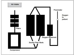
Flow Diagram of an Oxygen Concentrator Courtesy: Oxygen Concentrator Store
Please do not only see the output flow of an oxygen concentrator like 5litre, 10litre or so. the most important is to make sure you get 90% Oxygen at highest flow level.
Block Diagram of an Oxygen Concentrator
For a small family with no senior citizens a 5 litre at 90% oxygen concentration should be good enough.
For 2 senior citizens or for a big family 10 litre at 90% oxygen concentration should be good enough as it can support 2 patients at once if the need arises. And can assist senior citizens during home critical care if the need arises.
Please do not get fooled and pay big money for small oxygen concentrators sold by highlighting 5 Litre and 8 Litre and do not give an output of 90% concentration of oxygen at higher flows which is the need of the hour.
Please read the specs well and if required please ask your supplier to show you the oxygen output on an oxygen analyzer at higher flow of 5 Litre or 10 Litre.
Also most importantly consult a doctor before you invest your hard earned money in the device. Right now, because of a shortage of oxygen supplies, the concentrators are overpriced. As soon as supply meets demand, the price of concentrators will come down.
‘Recovery’ in mental health a human rights issue
It may be a common sense assumption that when someone enters the world of treatment for their emotional or mental health issues their intention is to be relieved of their suffering, emerge healed and whole from the treatment. But does it really happen? Is there any way to know how many people actually exit the (mental health) system? Is anything going on in the treatment process that can actually lead to someone’s recovery?
By and large experiences of vast numbers of people are that once they enter into the system they are told by psy-professionals (and other medical professionals) of all hues that they would now have to rely on psychiatric medication for the rest of their lives. This insistence on medication, which is borne out of the agreed upon knowledge which all psy-professions draw from, invalidates the day-to-day suffering of people into a predetermined ‘illness’ category, complete with a diagnosis and prognosis. In 2019, I wrote this article which can be downloaded or read here or here which problematizes this aspect of treatment and questions what the goals of such treatment are.
It may be common sense assumption that when someone enters the world of treatment for their emotional or mental health issues their intention is to be relieved of their suffering, and emerge healed and whole. But does it really happen? Is there any way to know how many people actually exit the (mental health) system? Is there anything going on in the treatment process that can actually lead to someone’s recovery?
Research suggests that recovery is mostly not a goal psy-professionals target when they start treating people for their mental health issues. For most people the starting of treatment itself is ‘recovery’ because according to professionals the fact that people’s suffering has been recognized is itself a great victory over their ignorance: of being a mere suffering, while it is actually a real ‘illness’. However the truth from a ‘patient’s’ perspective is that until people take pharmacological treatments they believe themselves to be ‘ill’ or ‘sick’ and therefore not quite recovered. From the ‘patients’ ‘ position it is the ending of the treatment process and exiting psychiatry that counts as real recovery, not interminable treatments. Whether or not mental illness is a real illness is itself a topic of big discussion and debate, which I postpone for another location as of now.
Knowledge about recovery missing
When there is a gap in the social knowledge about a situation it has consequences; both for individuals, families and society as a whole. For example until penicillin was discovered by Alexander Flemming, a number of people would die for reasons as simple as flu or pneumonia. Antibiotics gave a new lease of life to people around the world and heralded a new era which cumulatively brought newer efforts that prolonged human life expectancy.
In the context of mental health when people are not aware that they can recover and they choose instead of continue taking medication, their lack of information is a knowledge or information gap. Instead of recovery their bodies become sites for testing newer drugs, yet no advancement produces the desired ‘cure’. When drug treatments continue for decades people not only become chronic patients, they also slowly develop co-morbid conditions such as thyroid malfunctions, liver damage, akathisia (I have written about it here), seizures, lupus and scores of other conditions, not to mention the ‘regular’ issues of hypertension, diabetes etc.
A lack of information about the possibility of recovery, which leads to never ending treatments is the issue addressed here. This knowledge or the lack of it, also called epistemic ignorance in research, becomes an issue of justice first of all. When people have unequal access to information in society, even though we live in the information age: the internet having created unprecedented possibilities for diffusion of ideas, only the idea of rising incidence of mental health issues are widely publicized, especially by the media and myriad psy-professionals. Treatments that do not end and progressively disable people, making them socially outcast and confined to their domestic spheres become an issue of justice- for what then are these treatments intended for?
Why human rights issue
When a patient or their caregiver is told by a psy-professional that their treatment is for life more often than not they do not question it, but accept the ‘diagnosis’ as a truth or fact. Treating people and the inability to produce a healing or cure, or letting them exit psychiatry by supporting drug withdrawal is not common or heard of. Long periods of remaining on these drugs makes people more and more disabled and socially marooned for they lose the confidence to deal with life, situations and other people.
The information of recovery is a right to knowledge about the idea of recovery. It is a right of every person who is on drug treatments to know how long their treatments would be and what alternatives exist. Until people do not realize that their interests and rights are being compromised if they continue taking drugs passively it will not help them, while pharma corporations will keep making steady incomes and rising profits. This is a gap of knowledge which can only be filled by people who have taken the path of recovery or who understand the injustice of denying people the knowledge about their mind and body. In one of my future pieces I will write about how the new Mental Healthcare Act of 2017 also does NOT support recovery and ensures people remain ‘patients’ ad infinitum, once they enter into the mental health system (that being the work I did for my doctorate)
Thank you for reading. If there is something more you would like to know about recovery from mental health challenges, or have a personal concern, you are welcome to post a query or comment in the comment box below. Prateeksha would be happy to respond to it, if necessary, even with a new blog post.