Series’ Next “Surprise” -The Unexplored Mega Shear in Punatsangchhu-II Dam
– Another Dam Location That Too May Go / Have Gone / Could Have Gone Wrong Due To Unexplored Shear Zone Called “Geological Surprise”. Could This Shear Zone, If Went Unexposed, Have Repeated A Punatsangchhu-I ?
( Second of the incidences of a chain of massive surprises in the two Punatsangchhu Projects in Bhutan )
* Are All Geological Surprises, Logical Geo Surprises ?
In the series of strange coincidences of “geological surprises” , which happened in the two mega hydroelectric projects named Punatsangchhu -I & Punatsangchhu-II H E Projects, under construction since 2009 -10 in Bhutan, the present case is of a suddenly encountered mega Shear Zone, which cuts across from heel to toe, the foundations of four dam blocks, in an effective width maximum of 30m and running in depth more than 13m. This surprise came despite the very dam site having been explored by the Consultants in the DPR ( unlike the case of Punatsangchhu-I dam where a mega shear zone was ‘surprisingly’ encountered supposedly because the dam site was not the one, which was studied by the Consultants in DPR).
- The structural damage control seems to have been done with shear zone treatment , but at a great cost both in terms of the big time delay of more than one year and extra cost of Rs. 387 million, put to the Project in exploring the shear zone and treating it. However, the success of the Shear Zone treatment would be tested with time.
The Punatsangchhu-II (PHEP-II), a 1020 MW project with a new approved project cost of Rs. 72900 millions ( US $ 1.04 billions), possibly to be further escalating to Rs. 75000 millions ( US $ 1.07 billions), with already incurred cost of about Rs. 65880 millions is delayed for two reasons. Firstly the delay of more than one year was caused because the Dam foundations had encountered, a that far unexplored, mega shear of maximum 30m width, which cut across the length of the 4 dam blocks diagonally, traversing from heel to toe. The shear zone with its 35ᵒ to 45ᵒ dip, continued under the foundations to large depths. Secondly, a further delay of four years, so far, in implementation of the Power House Complex, has already crept in due to the huge rock mass failure which happened in its underground Downstream Surge Gallery (DSSG), resulting in formation of a huge cavity of about 91m height x 70m length and 45m width in the crown of the DSSG.
Occurrence of too many geological surprises, which were blamed for the big mishaps in the two mega Projects Punatsangchhu – I & II ,intrigues one to investigate if ‘ harping on the geological surprises‘ was only a scapegoat for the lack of proper geological investigations done by the Consultants and inappropriate design of rock support measures done by the Designers, who were same for both the Projects.
The Case of Mega Shear Encountered In PHEP-II Dam Foundations
1. Geology at Dam Site :
Geologically, the area at the dam site exposes variety of gneissic rocks such as quartzo-feldspathic biotite gneiss, banded gneiss, augen gneiss, and thin seams or bands of biotite schist. These rocks are intruded by leucogranite and pegmatite. The right bank is comparatively steeper and occupied by well exposed rock outcrop. Whereas the left bank is largely occupied by overburden consisting of talus and thick slide debris with some rock outcrop exposed at higher reaches. On the left bank foliation trend varies from N-S/400E to N700E-S700W/150SE whereas on the right bank it varies from N800W-S800E-320/S100W to N500E-S500W/300-350 S400E. This swing in foliation is due to warping in the rock. However the general trend of the foliation is N600-700E to S600-700W/300SE. The rocks are moderately to highly jointed, traversed by four to five prominent joint sets and shear zones up to 50cm thick. In general the foliation is dipping into hill side; indicates an anti-formal structure.
2. Geological Investigations at ‘Detailed Project Report’ Stage Failed To Detect The Major Shear Zone In Dam Foundations
In the DPR stage, in the geological investigations carried out by the Consultants, a total of 11 nos. of holes were drilled at the proposed dam location for ascertaining the rock-overburden contact and depth of fresh rock for deciding the foundation level of various blocks. On the basis of these DPR stage drill core examination, the deepest foundation was proposed at EL 760.0m by the Consultants in the DPR. No major Shear Zone were detected to be present at dam site as per DPR stage explorations and geological investigations done by the Consultants (See Fig. -1).
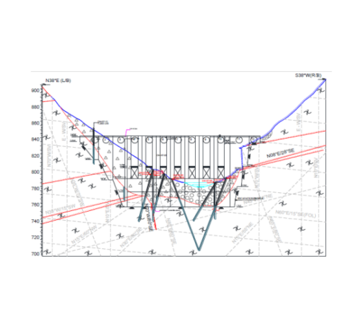
Fig. – 1
3. Geological Investigations At Construction Stage :
Weak features were encountered during dam excavation /stripping of the left bank, which were not reported in the DPR stage investigations done by the Consultants. Actual rock profile at EL 825.0m, in the Left bank was found shifted by 14.5m towards hill side from that suggested by DPR stage investigations .
In view of this discrepancy a detailed investigation was felt required to be done to ascertain the sound foundation grade rock and to also decide stripping limit. Subsequently, during construction stage, keeping in view the change in anticipated rock slope profile, 12 nos. of drill holes ( See Fig.-3) were drilled at EL 825m to reconfirm the rock overburden contact and foundation grade rock at the dam bloc nos. 1, 2, 3, 4 & 5 located near the left abutment. As the fresh rock was encountered at higher level as compared to DPR stage investigations, the of block nos. 4, 5, 6, and 7 have been founded at EL 765.0m, instead of at EL 760.0m.
During these construction stage exploratory drilling, on the left abutment, weak rock mass zone with sandy horizon encountered in the DH-10 and 12 ( See Fig. 3). From the drill core logging it had been interpreted that sand and crushed rock pocket exists from EL 763.4m to El 759.40m, however that time direction and inclination could not be confirmed.
The drill holes in the river bed area established to have a maximum depth of fluvial fill material/overburden of 52.50m (DH-9: located in block no. 5, 35m d/s of dam axis). The maximum depth of the quaternary alluvium/overburden in the river valley under the dam axis is 45.60m (DH-14: located in block no. 3, at dam axis).
General level of the exposed bedrock in the overflow dam section varied from EL 765.0m in dam block no. 4 to EL 755.0m in main dam pit (block nos. 8, 9, 10). The rocks exposed at the foundation grade comprised predominantly quartzo-feldspathic-biotite gneiss, biotite gneiss, and leucogranite. These were intruded by veins of leucogranite, quartz and pegmatite. The foundation rocks were traversed by a number of shear seams and most of them were of short continuity and restricted to a single dam block.
* Still no major Shear Zone was detected in this detailed geological investigations done by the Consultants during excavation of dam pit.
4. Additional Geological Exploratory Drilling Necessitated Yet Again During Further Dam Excavation
As mentioned above, 12 nos. of holes were drilled during excavation stage in view of the discrepancy observed against the DPR investigations. A 4.0m thick sand pocket was found resting over highly fractured and crushed rock mass near proposed joint of block nos. 5 & 6 when had been probed during drilling of hole nos. 10 & 12 at RD 87.0m & CH 16.0m & 27.0m respectively below proposed block joint of 5 & 6. Considerable water loss was observed during drilling and sand was first appeared at EL 763.0m during drilling hole no. 10 and continued up to EL 758.5m. The rock strata encountered immediately below sand deposit was found highly fractured and crushed up to the EL 749.90m. The same sand deposit was further reconfirmed through hole no. 12 drilled at RD 87.0m & CH 24.0m downstream where it is appeared from EL 760.27m to EL 758.77m, resting over highly fractured and crushed rock mass up to EL 755.77m. In view of uneven bed rock profile four drill holes were carried out to decipher the sound foundation grade rock below the EL 822.0m and on the basis of interpretation of borehole core logs, the dam block no. 1 was lowered up to EL 795.0m (instead of EL 825.0m) and block no. 2 rested at EL 785.0m (instead of 798.0m).
Subsequently, during further progress of excavation on left bank of dam being done concurrent to drilling of above mentioned additional four holes, a shear zone (550-600 / N0700 to 0900, affected zone varies from 3.5m to 5.6m, Clay gauge >20cm, with crushed/fractured rock mass) encountered askew to the river flowing direction passing from u/s to d/s (heal to toe of the dam).
The Shear zone was encountered in all these additional four drill holes at different depth with variable thickness.
5. Investigations, delineation and interpretation of the Shear Zone
With the progressive excavation, when the excavation in block no. 6 & part of block nos. 5 & 7 excavation (EL ~765.50m) was in progress the major shear/weak zone was encountered in all these blocks.
Sub-surface investigation was done through those additional four boreholes, mentioned earlier above (DH-13 to DH-16), with total depth of 187.0m, drilled on the dam site (dam foundation blocks 4, 5, 6 and block joint of 5 & 6), to ascertain the thickness, depth and behaviour of the shear zone. Frequent change in attitude of shear zone, was observed.
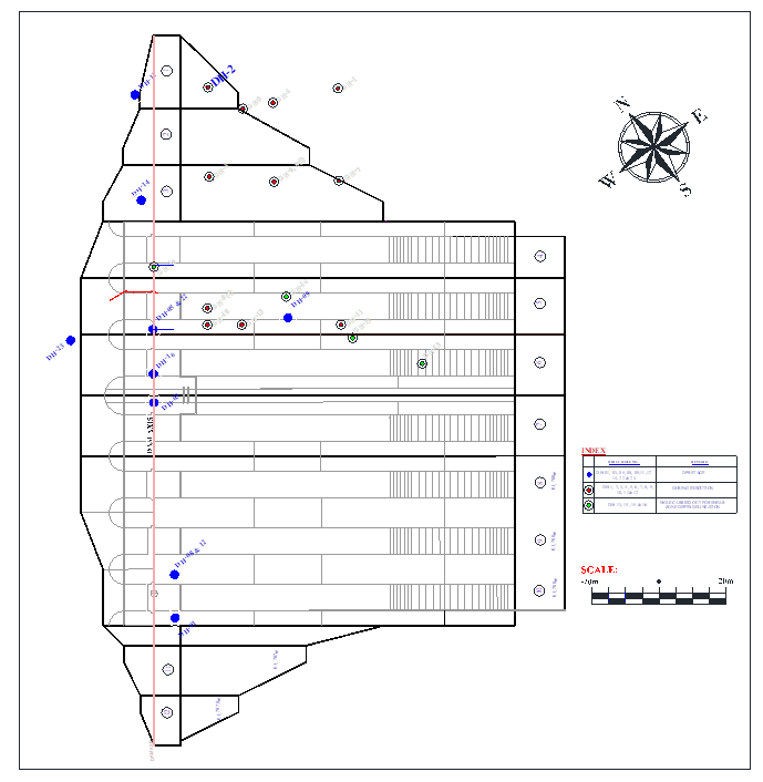
Blue Points – DPR Stage Holes, Red Points – Construction Stage Holes,
Green Points – Additional Holes Done in Construction Stage for Delineation of Shear Zone
Fig. – 2
Shear zone with varying thickness of clay gouge material and affected zone (approximately 3.5m to 6.5m) was encountered in the main dam pit area in the block no. 8 (at EL ~755.0m: near toe of dam body) and in the inclined foundation of the dam block no. 7 (below EL 765.0m) and below dam block nos. 5 & 6.
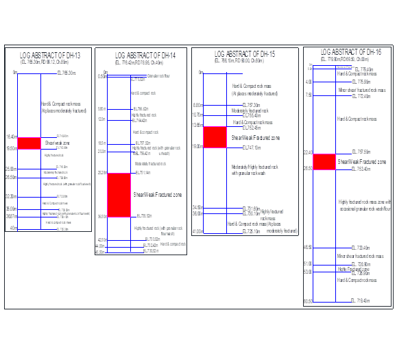
Fig. – 3
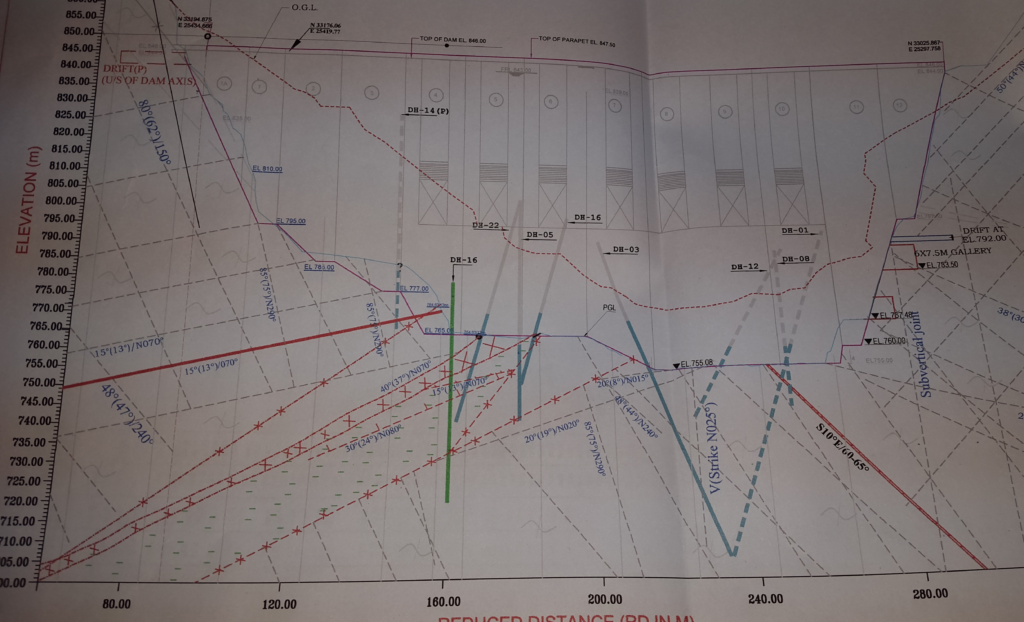
Fig. – 4
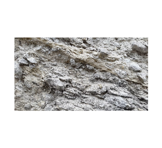
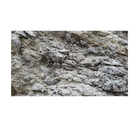
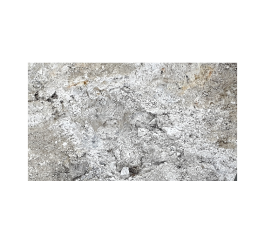
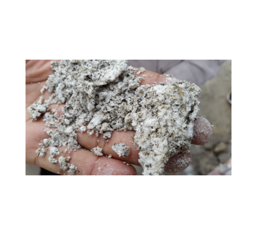
The encountered rock mass, in the drill holes, comprises predominantly quartzo-feldspathic-biotite-gneiss (QFBG), biotite gneiss, leucogranite with bands of biotite schist of variable thickness. At places the rock mass is intruded by thin veins/patches of pegmatite. Shear material mainly comprises highly pulverized rock mass, granular rock flour, fractured rock mass, clay gouge with slush, and broken rock fragments.
The drill core logging revealed that the shear zone depth varies from 3.1m to 11.22m and affected/fractured rock mass zone below the shear zone varies from 6.0m to 20.0m in depth.
The shear zone is traversing from dam heal (block no. 5), dam centre (block no.6) to dam toe (block no. 7) having curvilinear nature, however, it is encroaching in block no. 4 by ±1.0m near RD 73.0m in a limited area; between CH ±18.69m and CH ±20.0m at EL 765.0m and in block no. 8 d/s portion it is intersecting between CH 97.0m and CH.102m at El 755.0m. The general trend of shear is 350-420/N 0700 to 0800.
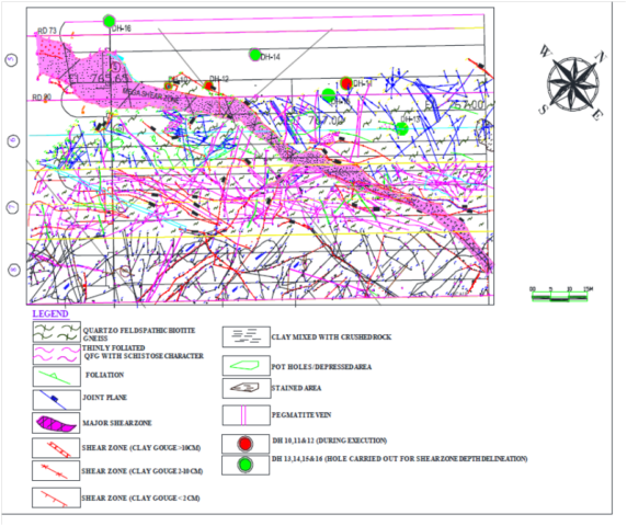
Fig. – 5
However, there is variation in the shear’s attitude due to warping of foliation and its curvilinear nature. In the block no. 5 the thickness of shear zone (including fracture zones and affected zones) at the dam axis is 13.97m whereas, in the u/s part of the dam (near CH ±20.0m) it is 14.19m thick. Sheared material comprises moist clay gouge (0.5m to 1.0m thick), rock flour, crushed/fractured rock, fragmented rock pieces and intermittently hard patches of parent rock (no strain zones). The affected zone varies from 4.0m to 30.0m.
The foundation surface in the mapped area is undulatory due to intersection of different joint sets and formation of wedges. The geological mapping revealed that the mega shear zone is bounded by two shear zones (SZ-1, forming left side boundary, having clay gouge thickness 5cm -20cm and SZ-2, forming right side boundary, having clay gouge thickness 8cm – 100cm) passing through block nos. 5, 6 and 7 from upstream to downstream direction, dipping into left abutment side, and having variable thickness.
Infilling material of this weak zone comprises crushed rock mixed with minor clay and at places small lenses/chunk of QFG. The width of this zone varies from ±7m, at u/s side near dam axis, to ±2m at d/s side. The attitude of its two boundaries i.e. SZ-1 (200-550/N0700-1000) and SZ-2 (200-550/N0500-1100 also vary from u/s direction to d/s direction at different places. Besides, major shear there are 13 nos. shear seams were recorded during foundation grade mapping.
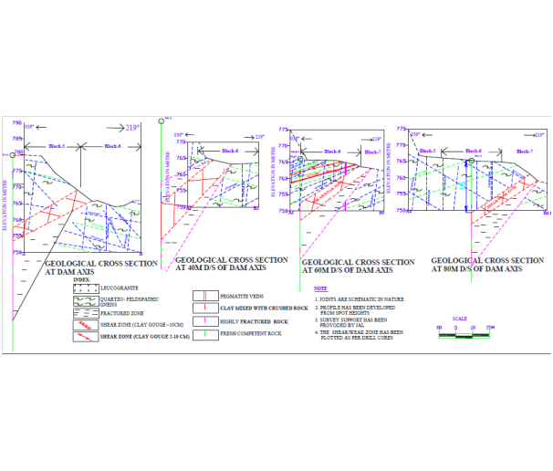
at Dam Axis and at Ch. 40m, 60m and 80m D/S of Dam Axis
Fig. – 6
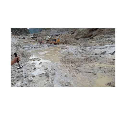
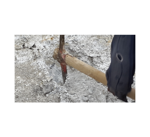
Photographs of Shear Zone
 |  |
 |  |
 |  |
6. Treatment of the Shear zone
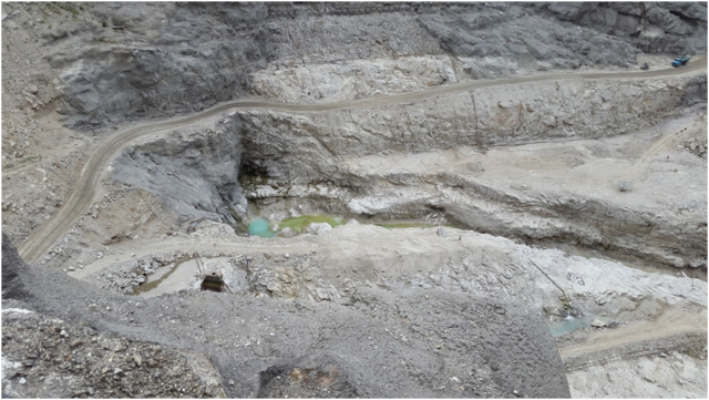
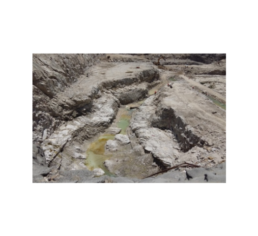
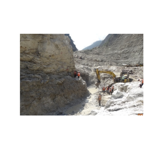
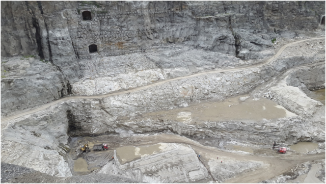
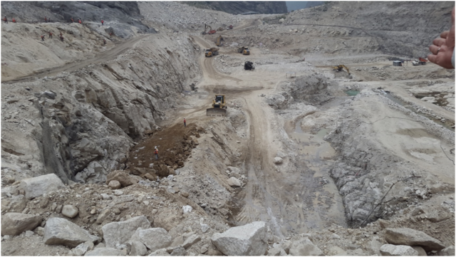
Finally, a 125.0m long, 5.0-35.0m wide and 13.0-15.0m deep shear trench was made in order to treat the shear. The field observation suggests that this shear is a discrete fracture between blocks of rock containing several parallel or anatomizing(i.e. branching and reconnecting) shears particularly at the toe of dam body near dam block nos. 7 & 8 and may have formed in brittle ductile regime.
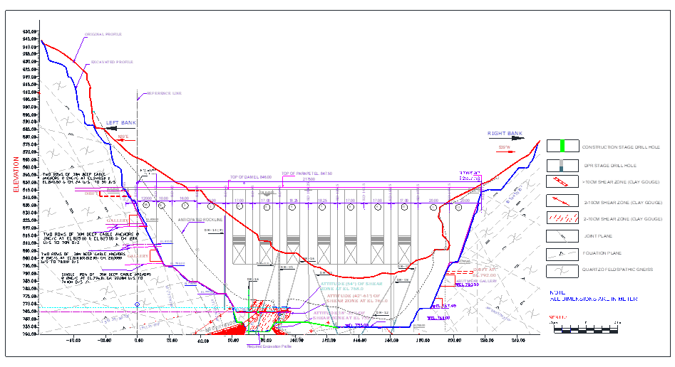
Fig. – 7
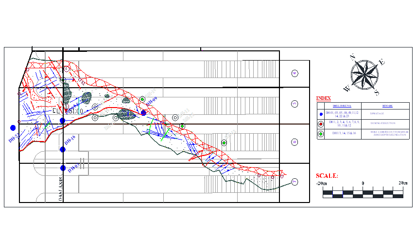
Fig. – 8
Photographs of Shear zone trench excavation
 |  |
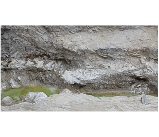 | 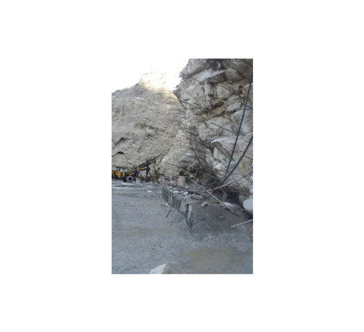 |
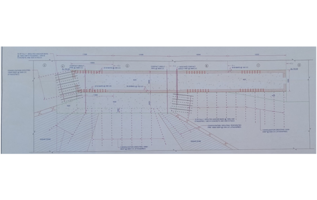
Fig. – 9
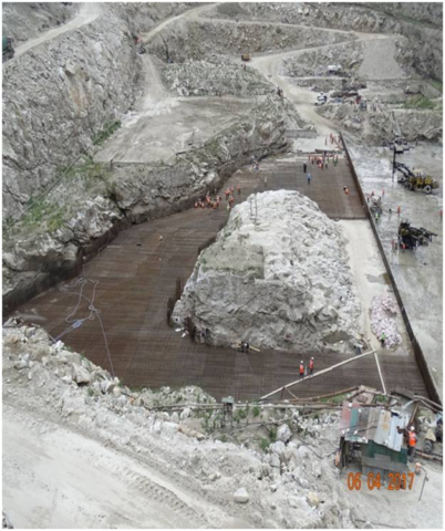
* The Shear Zone though has been replaced in its depth of 13m by RCC Plug, its performance with time would need to be watched.
The consultants had failed to detect and delineate the Mega Shear Zone in the Geological Investigations which formed the basis of selection of the respective Dam Sites, in both the cases of Punatsangchhu-I and Punatsangchhu-II HE Projects. In the case of Punatsangchhu-I a major slide of right bank on the shear zone has halted the dam construction by 7 years as of present. In the case of Punatsangchhu – II, the detection, delineation and treatment of the shear zone delayed the dam construction by more than a year. The treatment and strengthening of shear zone in both cases has made huge time and cost over run in the Projects.
The excavation of the Shear Zone involved excavation of 43 million cubic metres in sheared rock/ fractured rock mass. The Shear Zone trench was refilled by M25 grade and M20 grade of cement concrete provided with 2200 MT of 32mm dia. steel reinforcement . The consolidation grouting done through combination of Multi Stage and Single Stage grouting in the shear zone area, as per my information, consumed 8 bags of cement per hole, thus aggregating to total consumption of 9297 number of cement bags. The grout acceptance experience in the affected area after excavation of the Shear Trench gives an indication of the clay content in the fractured rock material present under the shear zone. The Shear Zone treatment has costed Rs. 387 million and more than a years delay to the Project.
The Shear Zone was missed by the Consultants in the drill holes no. DH5, DH9, DH10 , DH 12 and DH22 which were done in the Dam Block no. 5 at DPR stage and later in initial construction stage, despite their location being almost the same as that of additional four holes DH13, DH14, DH15 & DH16 in which the Shear Zone was intercepted at the end during excavation at the behest of Project Geologist and Project Engineering and Construction Agency team.
The massive Shear Zone had been finally detected and treated.
* However, the debatable point is that if the presence of this massive Shear Zone of that great a size , which affected foundations of four numbers of dam blocks from heel to toe, in a maximum width of 30m and depth more than 13m , had been detected at DPR stage, then, should this very site been preferred as dam site ?
* In case the answer is NO, then whether construction of the dam here at this site is a compromise of a sort ?
The detailed paper co-authored by me “Delineation and treatment of Mega shear zone in the main dam foundation : A case study of Punatsangchhu HEP-II, Bhutan” was selected for 26th ICOLD Congress” held in July on 1-7-2018 at Vienna, Austria. The Paper was also selected for oral presentation.
( Second of the incidences of a chain of massive surprises in the two Punatsangchhu Projects in Bhutan )


