
A Case of ” To Be Or Not To Be A Fit Site For 300m Deep Dam Foundations”


PUNATSANGCHHU-I DAM – RIGHT BANK FAILURE
You can listen to the Presentation and discussion on the failure of right bank at Punatsangchhu-I dam site, held on DDAG Open House, given at link : https://lnkd.in/dPGjpJk
( First of the incidences of a chain of massive surprises in the two Punatsangchhu Projects in Bhutan )
– Huge Setbacks Due To Failed Assessments Of Geology & Rock Supports
There is a strange coincidence of huge rock mass failures, which happened in the two mega hydroelectric projects named Punatsangchhu -I & II H E Projects, under construction since 2009 -10 in Bhutan.
The Punatsangchhu-I Hydro Electric Project (PHEP-I) a 1200 MW project with scheduled commissioning date of year 2016 and at sanctioned cost of Rs. 35146 millions and new approved Cost of Rs. 94000 millions (US$ 1.34 billions), is expected to have further escalating its cost possibly to Rs. 121000 millions (US$ 1.74 billion). The Head race tunnel and Desilting Arrangement lying completed since 2015, Powerhouse complex 98% ready have an already incurred cost of about Rs. 80000 millions .
However, even the start of concreting for construction of 136m high dam is a big uncertainty after its Right Bank suffered a massive slide with continued movement of the big hill mass about 500m height towards valley and downstream by 5m and vertically subsiding by 5m in a week in July 2013.The hill mass movement has continued at slower pace for more than year, sliding on SZ-2 Shear Zone.
A whopping cost of about Rs. 30000 millions, out of above cost, may get attributed to extra works necessitated because of ” geological surprises”.
The Punatsangchhu-II (PHEP-II), a 1020 MW project with scheduled date of commissioning of year 2017 at sanctioned cost of Rs. 37778 millions and a new approved project cost of Rs. 72900 millions ( US $ 1.04 billions), possibly to be further escalating to Rs. 80000 millions ( US $ 1.14 billions), with already incurred cost of about Rs. 65880 millions is delayed due to the huge rock mass failure in its underground Downstream Surge Gallery (DSSG), resulting in a huge cavity of about 91m height x 70m length and 45m width in the crown of the DSSG. The Dam foundations had encountered, a thus far unexplored, mega shear of maximum 30m width, cutting across the length all the 4 dam blocks diagonally. The shear zone with its about 35ᵒ to 45ᵒ dip, continued under the foundations to large depths.
Again a whopping cost of about Rs. 15000 millions, out of the above cost, may get attributed to extra works necessitated because of ” geological surprises”.
Occurrence of too many geological surprises, which were blamed for the big mishaps in the two mega Projects, intrigues one to investigate if ‘ harping on the geological surprises‘ may only be a scapegoat for the lack of proper geological investigations done by the Consultants and inappropriate design of rock support measures done by the Designers, who were the same for both the Projects .
The Case of Punatsangchhu-I H.E Project Dam Right Bank Failure :
1. Selection Of The Dam Site Without Detailed Geological Investigations
( the first miss)
The present dam site was selected in 2009 at a new site, located 1.5km upstream of the original site which was considered in the Detailed Project Report (DPR). The shifting of location to the new site was done just before taking up the Tender activities of the Project. The selection of this new site was done on the basis of some geological explorations done at different times earlier, apparently with a purpose of studying geological conditions of the reservoir rim. The Tender Drawings of Geological Details, issued in 2009 , showed the geological conditions that were based on the limited exploration done till that far. The Tender stage geological drawings at the dam axis and at various sections upstream and downstream indicated no Shear Zone to be encountered. The tender stage Geological Sections at Dam axis and at 100m downstream are placed at Fig -1 and Fig.- 2 below.
- Tender Stage Geological Drawings of 2009 Show no Shear Zone in Right Bank :
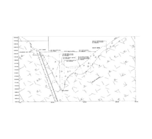 |  |
| Tender Drawing of Geological Section At Dam Axis Fig.- 1 | Tender Drawing of Geological Section At 100m D/S of Dam Axis Fig.- 2 |
2. Geological Assessment done By The Consultants in 2011 , At Design & Construction Stage Did Not Detect The Presence Of The Massive Shear Zone And Delineate Continuity Of The Shear Zone In to Hill At Vulnerable Dip :
( the second miss)
The Geological Investigation at the present Dam site was carried out during 2010 – 11 by the Consultants after issue of Tender Specification Drawings for deciding the stripping limits and designing the rock support system for excavation of the dam pit. The excavation for the 136m high dam foundations involved excavation of a depth of 300m.
Earlier Consultants had shown lacksidal attitude when they did not carry out detailed Geological Explorations for Selection of Dam site in 2009. This was followed, apparently, yet by a limited explorations done in 2010-11 to decide the stripping limit and design the excavation support details of the right bank slope of 300m excavated depth.
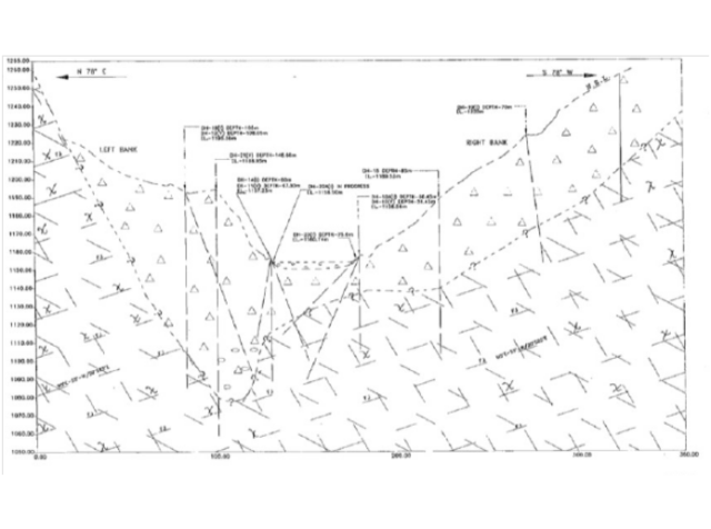
- Did The Construction Stage Geological Drawings of 2011 Missed To Connect Intercepts of Sheared Rock Mass In Drill Holes And Delineate The Steep Show Shear Zone in Right Bank ??

Fig.- 3
Sheared Rock Mass Intercepts Recorded in Drill Holes
The sheared rock mass intercepts were recorded in the Drill Holes DH25, DH31 located at dam axis and DH26 located at 20m D/S of Dam axis and in drill holes at further downstream in the geological investigations carried out by the Consultants during construction stage for excavation support designs .
- Apparently the Consultants had failed to connect these intercepts of sheared material found in different drill holes to establish the extent and the vulnerable dip the major shear zone would have, though they had detected presence of the sheared rock material in these explorations.
Logically, after the sheared material was intercepted in different drill holes, it should have been investigated whether the intercepts were a part of one single Shear Zone. More exploratory drill holes may have been done further up the hill to connect the intercepted sheared material incidences and delineate the attitude of the Shear Zone, of which these intercepted shear material could be possibly a part of. Thus the inaccurate geological assessment was made by missing to interpret and detect continuity and rising dip angle of the major Shear Zone in right bank of PHEP-I dam site.
- The required further geological investigation does appear to have been missed by Consultants despite that the Resident Geologist of Project Authority had provided the Consultants the following detailed geological note which clearly mentioned presence of shear zones and brought out the possibilities of slides happening on the shear zone.
3. Geological Assessment by the Project’s Senior Resident Geologist, at Construction Stage in 2011, Reported Presence of the 1.5m Thick Shear Zone , Prone To Sliding And Its Need for Proper Strengthening Which Was Neglected By The Consultants :
( the third Miss )
The Geological Report of 2011 of the Sr. Resident Geologist of the Project is reproduced below :
“The strata shows small scale, S- shape tight folds and broad warping of the beds at places, indicating that the rock strata has undergone the polyphase deformation in the past leading to development of numerous criss-cross structural discontinuities like joints, shears etc. of different orders. Five prominent and two random joint sets are recorded in the right bank. The foliation is very close to moderately spaced from 2cm to 60 cm and dips towards valley slightly in d/s direction; however rolling of dip is observed at places, there it dips into the hill due to folding and warping. The general topography and gentle natural slopes on the right bank of river are controlled by low and valley ward dipping foliation planes.
The drilling data on right abutment has indicated the presence of numerous thick deformed/sheared zones/schistose rock mass having very poor RQD (below 30%) and nil to poor core recovery (below 40%) at different depths. Such rock mass is fissile and fractured, which breaks along foliation and other prominent joints and has very low strength. One deformed zone/band (1m thick) along foliation is delineated at Ch. 13m d/s of dam axis at El. 1220m and at Ch. 23m d/s of dam axis at El 1205m and dips at 150-250 in the downstream.
A ± 15m thick band of fractured, biotite rich gneiss with schistose partings and sheared seams, which dips gently towards valley along foliation was delineated during drilling and is expected to expose in all along the foundation of dam block nos. 7, 8, 9,10 &11, and below the foundation of block nos. 12 and 13. The core recovery and RQD in this rock mass are very poor. Such bands striking parallel to the flow and dipping towards valley may form passage for water and are prone to slide under forces, hence require proper treatment during excavation.
Another shear zone (± 1.5m thick), which was encountered in the drift strikes from d/s to u/s and dips gently into the hill slightly towards upstream. This shear zone is expected to expose in the foundation of dam block no.11 at El ±1165m and below the block no. 12 along its dip & in the reservoir along its strike in the upstream. Such shear zone also needs proper treatment and strengthening as they form the avenues for water draining from reservoir and development of the hydrostatic pressure.
Layered/stratified/foliated rocks with softer beds (schistose partings/shear zones) confined between harder beds are always prone to shear stress problems/sliding, which inevitably develops in the rock in conjunction with pressure/load.“
- Geotechnical Problems Identified in the 2011 report of the Resident Geologist :
- Layered/stratified/foliated strata with soft bands confined between hard rocks.
- Occurrence of folds and warping indicating the signs of deformation and presence of local stress areas.
- Presence of thick shear/fracture zones and biotite rich bands of gneiss/schist having very low strength and less RQD.
- Moderately jointed and very blocky nature of the rock mass with steep joints having longer continuity and persistence, striking along the flow direction.
- Valley wards dipping foliation and prominent open joints.
- Formation of wedges due to intersection of the prominent joints.
- Presence of the parallel discontinuities with variable zones of permeability. Moderate to high lugeon values indicating the fracture permeability and fissured rock mass.
- Low to moderate strength of rock mass.
The above report shows that there was adequate warning given in the 2011 geological report by the Resident Sr. Geologist of the Project Authority of a 15m thick fractured rock mass present all along the foundations of dam blocks 7,8,9,10,11 and 12, with shear seems and dipping in to the valley, having potential of sliding . The report also informed of the 1.5m thick Shear Zone dipping in to the hill which would be getting exposed in excavation of dam blocks 11 and 12 . The report further warned that the layered/stratified/foliated rocks with softer beds (schistose partings/shear zones) confined between harder beds are always prone to shear stress problems/sliding.
- The report specifically asked to provide adequate support and treatment which apparently was not so designed.
The Rock Support Measures comprising only 150mm shotcrete and 32mmDia. 7.5m Long rock anchors , would have been designed in 2010 -11 based on the limited information gathered by the Designer / Consultant and not inferring and analyzing the sheared rock mass occurrences as a Shear Zone. Probably the Cable Anchors may have been found required to be provided , if analysis of the excavated slope would have been done incorporating the Shear Zone. However, there were no cable anchors designed for the Right bank excavation support, while provisions of cable anchors were done in Left bank excavation profile. Therefore, the rock anchors and shotcrete would have not been designed to hold the excavated profile of the Right abutment against a potential slide on the shear plane, as no such Shear Zone had been identified by the Consultants till that time. The designed provisions thus must have been under provisioned to safeguard a 300m deep excavated slope against the later resulted Massive Failure of Right Bank during its excavation in July 2013.
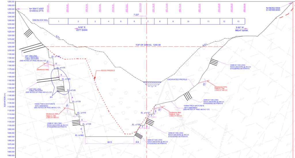
Fig. – 4
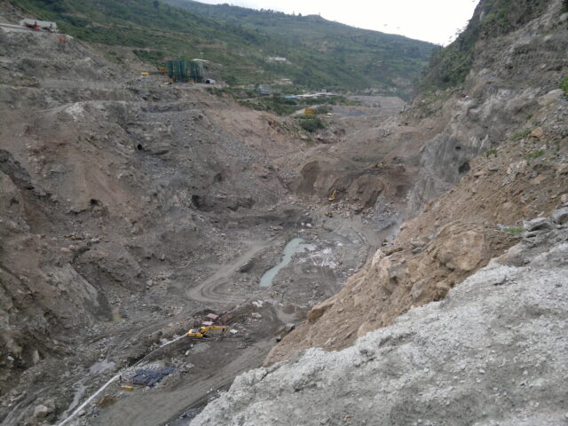
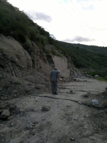
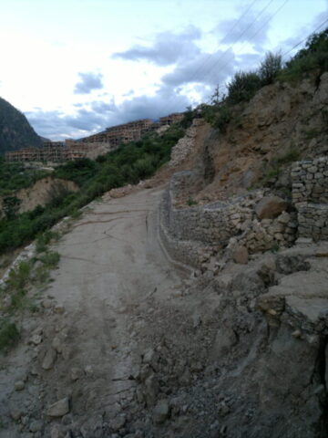
4. The Excavation Stages From 2010 To July 2013
 | 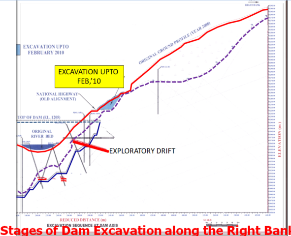 |
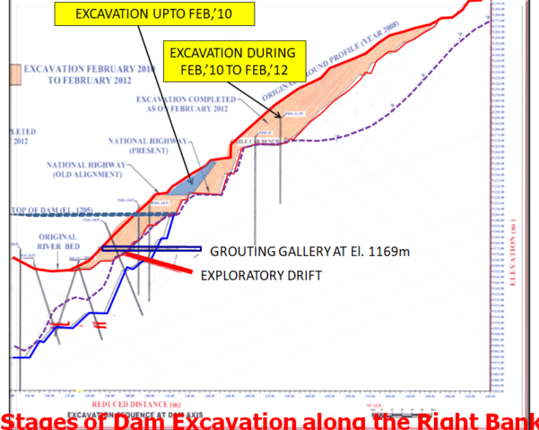 | 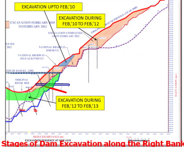 |
Figs. 5 to 8
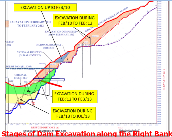 |
Fig. – 9
5. Incidental Identification of the Presence of the Shear Zone :
- Considering the weak rock mass condition, a 5.5m x 5.5m wide and 60m long gallery/tunnel with 15m long x-cuts in upstream and downstream side was excavated in right abutment (Dam Block-13) at invert El 1169m, in 2011 to February 2012, for consolidation grouting.
- Until July 2013, the excavated Right Bank Profile stood intact with provided support comprising 32mm Dia. 7.5m long Rock Anchors and 150mm Shotcrete.
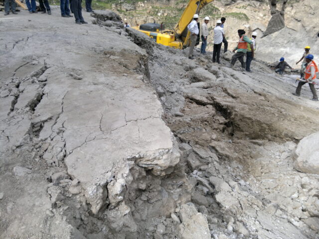
It was on around 10 July 2013 , subsequent to a Shear Zone getting exposed, that a few cracks were observed on the road surface which goes winding up on the Right Side Hill of the dam site, leading to the Project colony. Also the steel rib supports provided in the Grouting Gallery, at El. 1169m in the Right Abutment, were seen to be twisted and the invert floor of the Gallery was seen to have settled and developed cracks.
Immediately a team of the Consultants and the resident geologists of the Project visited the Grouting Gallery and prepared the following Geological Note based on their field observations :
6. Geological Assessment Note given by the Consultants on 12th July 2013 after observing cracks & Settlements in the Grouting Gallery in Right bank , Reported presence of Shear Zone Affecting 1.5m ~6.5m Thickness & dipping 250-450/N010-040 :
The Geological assessment Report of 12 July 2013 is reproduced below :
“ The entire excavated reaches of the grouting gallery and x-cuts have been supported with steel ribs (200 x 100mm) @ 1m spacing. The final lining and grouting through the gallery is yet to be done. Recently some settlement/deformation is noticed in the gallery and x-cuts. Hence a joint inspection visit was made to the site on 12th July, 2013 for geotechnical assessment and remedial measures. The rock mass exposed in grouting gallery and x-cuts is jointed, very blocky and weathered quartz-biotite gneiss with thin schist bands and shear zones. The rocks are deformed in the form of folding and warpings and distressed in the form of open/wide/stress relief joints.
The rock mass encountered falls inpoor to very poor grade category (Rock class IV and V). One major shear/deformed zone (Clay gouge 30-200cm, affected zone 1.5 to 6.5m) dipping 250-450/N010-040 cuts across the gallery from RD 27m (left wall) to RD 48m (Right wall) and over the crown beyond RD 50m. Shearing effect is more beyond RD 34m as it forms hinge portion of the fold. This shear/deformed zone strikes from d/s of dam (closer to valley) to u/s of dam (Farther to valley) and as per projections it was expected to cut in u/s x-cut between RD 15m (Crown) to RD 35 (left wall) with less horizontal cover on right wall.
- The location and pattern of the settlement/deformation occurred corresponds to the disposition of the major shear zone in the gallery and x-cuts and mobilisation of its broken zone under pressure. The shear zone is low to moderate dipping and runs oblique to the main gallery from left to right wall along strike.
- Such settlements are time dependant deformations in weak/soft rocks occurred after completion of the excavation and installation of the primary support depending upon the load/pressure; stand up time of the rock mass and support provided.
- Once commenced, such deformations tend to increase with the time if structure is not provided with the strong support.”
The Consultants noticed presence of the major Shear Zone, for the first time, in July 2013 only during inspection of the Grouting Gallery. Where as, the Sr. Resident Geologist of the Project Authority had already informed of the 1.5m thick Shear Zone dipping in to the hill which would be getting exposed in excavation of dam blocks 11 and 12, in his note provided to the Consultants in 2011 . This Shear Zone had did get exposed, in July 2013, at El. 1110m in excavation of dam block no.12.
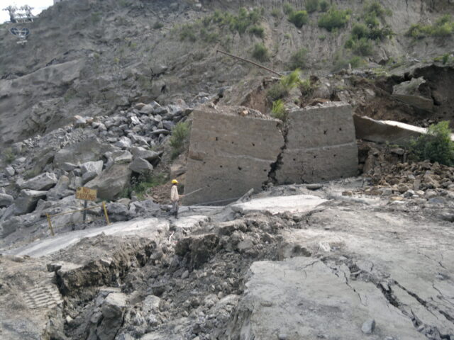
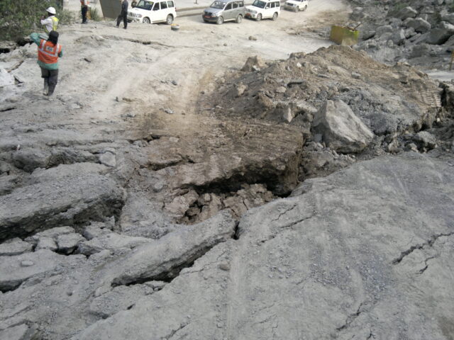
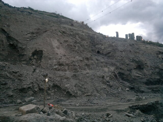
7. Massive Slide of 500m high x 300m long Hill Mass in Right Bank on 24 July 2013 :
Soon after the settlement/deformation was noticed in the gallery and x-cuts in the Right Bank, a massive slide in the Right Bank occurred which detached a hill mass in Right bank of a reach 500m in height , 300m in length and moved it over 5m towards the valley and 2m along the flow with 5m vertical subsidence. Cracks of about 10m to 15m depth appeared on the road and hill slope.
 | 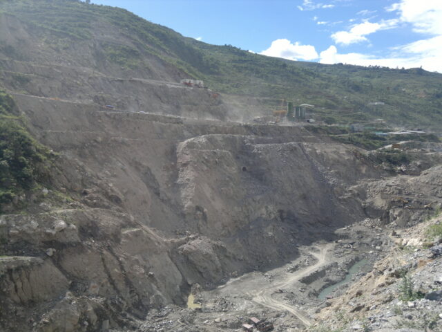 |
The right bank failure resulted in huge hill mass slide, causing separation of hill mass of about 500m ( 1/2 km) height , 300m length and 40-50m in its thickness under the ground surface. The slide created about 10m deep fissures at the top levels of slip in this stretch of the hill mass. This reach of the hill suffered subsidence/ settlement of the hill by 5m vertically and moved en-mass towards the river side by 5m and along river in downstream direction by 2.5m.
 |  |
 |  |
 |  |
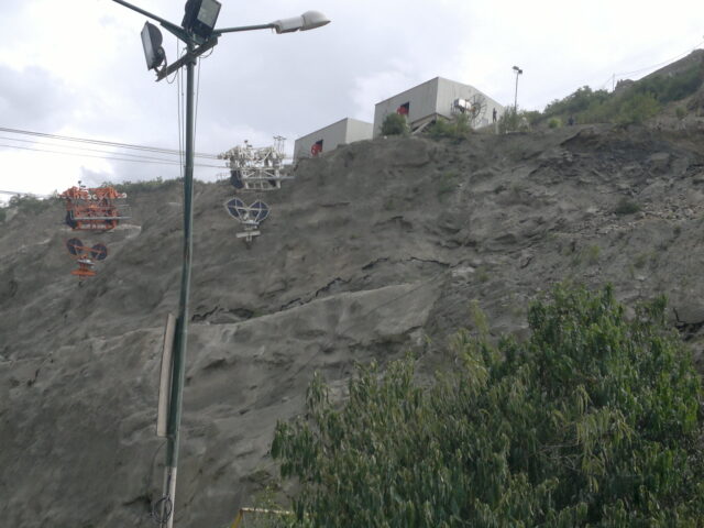
| The photographs below show the sagged Cable Car rope due to subsidence of foundations of their end anchors provided at a bench at El. 1250m in the Right Bank |
 |  |
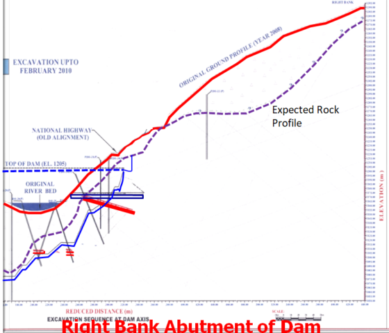
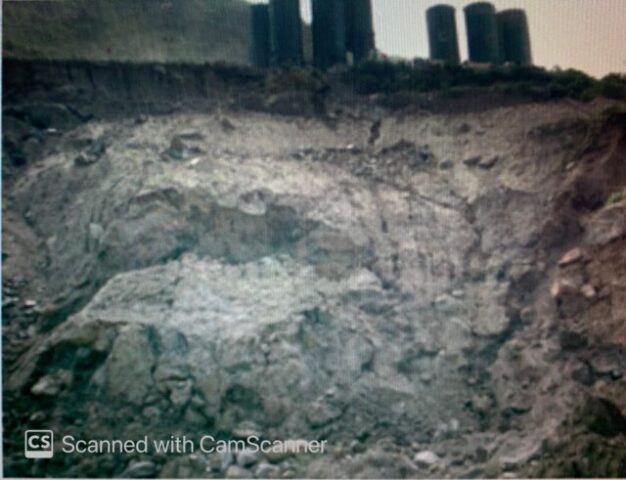
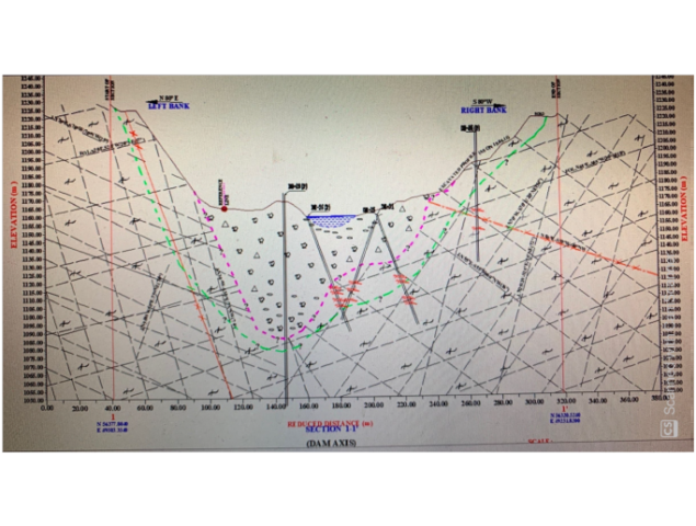
8. Delineation of the Shear Zone in the Right Bank
The hill mass stretch of over 500m height in a 300m length kept moving at faster pace for four days period, resulting in a shift of the separated big hill mass over 5m in to valley and over 2.5m along the direction of flow of river with a subsidence of the hill mass of 5m. The movement of this hill mass continued at smaller pace for days , weeks and months to follow. The hill mass seemed to have had slid over the Shear Zone. However the extent of the Shear Zone extending in side the hill was not known at that time. The cracks and fissures of about 10m depth had surfaced at locations as far till about 500m height of the hill.
The outer boundary of the hill surface affected by the massive slide was marked. A total 23 numbers of drill holes , running a total depth of 3500m were driven along the boundary of the slide affected area. The Shear Zone was delineated from the core logs .
(The excavated profile as existed post slide is shown in green color line)
Fig. – 10
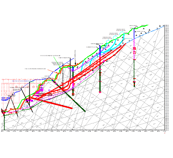
Comparison of Geological Assessments Done By The Consultants In 2011 Investigations V/s Actual Geological Conditions Encountered & Established in 2014 After The Massive Slide :
 | |
| The Sheared Rock Mass Intercepts Were Not Inferred, By The Consultants In 2011, To Be A Shear Zone Continuing In To The Hill Fig. – 11 | The Shear Zone SZ2, Delineated As Dipping Sharply & Deeper In To The hill Was established Through Additional Holes In 2014 , Only After 2013 Slide Fig. – 12 |
9. Synopsis of the Geological Investigations Done in 2009, 2011, 2013 and 2014 :
- The Consultants had failed to detect and delineate the shear zone in the geological investigations forming the basis of selection of the present dam site in 2009.
- The Resident Geologist reported in his Note in 2011, the presence of a shear zone SZ-2 assessed by him from the geological explorations done in 2011 for detailed design of slope excavation supports. But the Consultants / Designers had failed to build on gathered information and thus ignored to do further exploration to identify and delineate the continuity of the major Shear zone which extended in to the hill at a vulnerable dip angle.
- The Resident Geologist had reported, in his Note in 2011, of potential risk of slide along the Shear Zone and suggested proper strengthening. The Consultants apparently failed to do a slope stability analysis for the potential destabilised condition of the excavated slope in the Right bank arising from presence of the steeply dipping major shear zone, despite its warning given by the Project Authority.
- Therefore, the Consultants failed to design the appropriate support measures required to be provided during progress of excavation of the Right Bank, to ensure stability of the Hill Mass against hazard of a potential slide of the big hill mass , which eventually slid en-mass in its 1000m height, 300m length and about 30-40m depth inside the hill.
- Incidentally the Cable Anchors were provided at various levels in the Left bank excavated slopes, but the Consultants failed to establish the need of design and provision of Cable Anchors in the Right Bank to hold the endangered hill mass, which eventually separated out in the Right Bank and slipped over the Shear Zone.
- After the slide, a total of 3500m of length in 23 numbers of drill holes were done in 2014, along the boundary of the affected hill mass , which delineated the alignment of the shear zone.
- A more intelligent inference from the Sheared material intercepts in the drill holes done in 2011, would have established the need of a few more drill holes and detected continuity of the shear zone SZ-2 with its dip risingng sharply in to the Hill.
It may be seen that firstly there was lack of Geological Information gathered for selection of the present dam site. Thereafter, the inaccurate Geological Assessment was made by Consultants from the explorations that were carried out at the Construction stage for Designs of stripping limits of the excavation and Support Designs in 2011. Missing to connect the sheared material intercepts in detection of the Shear Zone had resulted in under provisioned design of the rock supports. The designed 32mm dia. rock anchors of 7.5m length were no match to and too insufficient than the required measures e.g. longer cable anchors like those provided in the Left bank . Thus the inappropriate and inadequate rock supports led to the major hill mass slide in the right abutment of PHEP-I dam, during its excavation in July 2013.
The slid hill mass has been in motion for years thereafter, though at much slower pace, despite a number of measures designed by the Consultants and implemented in the field to stall the movement of the hill . A number of more slides have happened in the downstream of the main slide, after 2013 till recently in 2018.
10. Strengthening Measures Implemented In Right Bank After Slide :

Fig. – 13
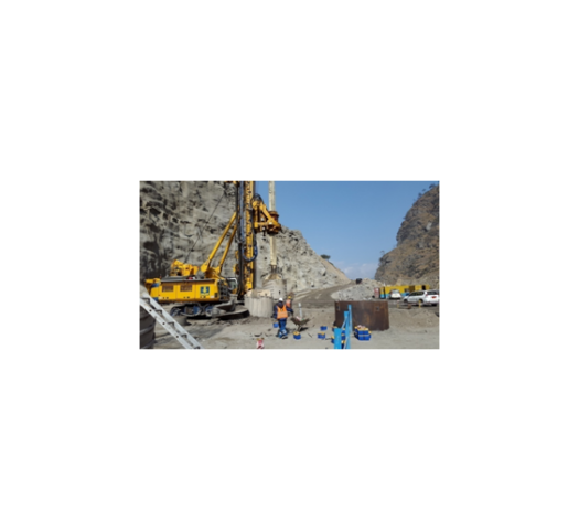
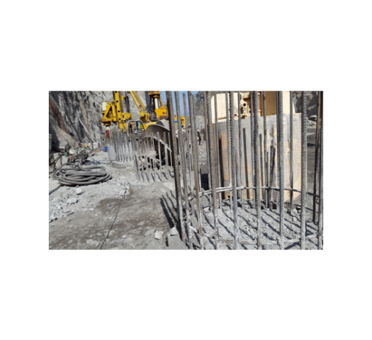
- After the slide, the Consultants designed installation of about 1050 numbers of 300mm dia steel encased micro piles from 11 different levels as a strengthening measure for the destabilised hill mass.
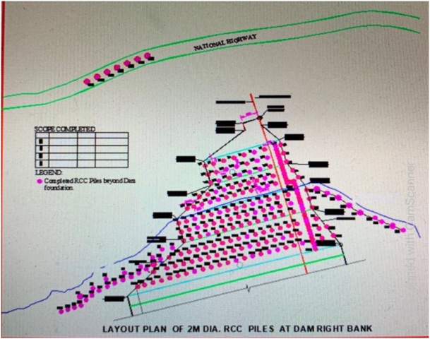
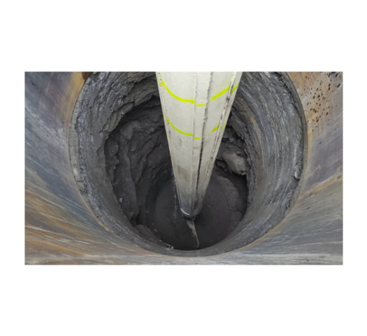
- Further also subsequent to the hill mass slide, bout 250 numbers of 2m diameter steel reinforced RCC piles of depth varying from 50m to 85m were driven from various levels along the excavated slopes. Each of these RCC piles were socketted in to sound rock for 10m length beyond the Shear Zone.
- About 50,000 MT of cement was consumed in grouting the slipped hill mass, carried out through 566 numbers of drill holes, totalling together to 123 kilometres of depth, to improve the deteriorated quality of the disturbed hill mass in local vicinity of dam axis after the slide as a strengthening measure.
- Also 1000 numbers of 100 MT capacity Cable Anchors from 12 different levels were installed.
- Important Observation :
It was experienced that during many instances of drilling, undertaken for installation of micro piles, the drill rod/ shaft used to drop for one to two meters depth, by itself without requiring any drilling effort, thereby indicating that the entire hill mass in the Right bank has been rendered geologically further weak & poor and porous resulting from the massive movement of the hill mass.
 |  |
11. Present Status in June 2020 :
- The right abutment hill continued to move for years after implementation of all of the above mentioned strengthening measures , but at reduced pace. The 2m dia piles too may have suffered some deflection.
- Norwegian Geotechnical Institute (NGI) has advised for off loading the right abutment by excavating and removing a huge part of overburden from the right abutment, starting from much higher levels, to improve its stability against sliding.
- A proverbial “stitch in time” in 2011 by adopting an adequate investigation, appropriate analysis and design by the Consultants may have saved from occurrence of massive rock failure in the Right abutment.
- The actual construction of the dam having halted since 2013, despite various strengthening and rehabilitation works being attempted to rescue the situation, there have been two more slides in the Right Bank in the immediate downstream of location of the massive slide of 2013 .
- However, after 7 years of the massive slide which happened in July 2013, even the start of concreting for construction of 136m high dam is a big uncertainty as of now in 2020. With about Rs. 80000 millions spent already, the future of the Project apparently hangs in uncertainty as of now.

Extremely well written. Comprehensive. Well researched. Congratulations @yoginder sharma ji
Thank you sir, for appreciating !!
Excellent case study. Ignoring the mportance of geological inputs has led to tremendous loss of time and money as well as delay in accruing social and financial benefits to the country.
Thank you sir for appreciating the article. It may be noted that Government of India is losing an interest to be accrued in the investment made so far of the order of Rs. 700 crores per year for last 4 years at least on an average calculated over the passed investment besides enormous increase in the cost of dam and rehabilitation of the site going to the order of additional Rs 3000 crores that too if it can make the Project complete. No questions raised ….